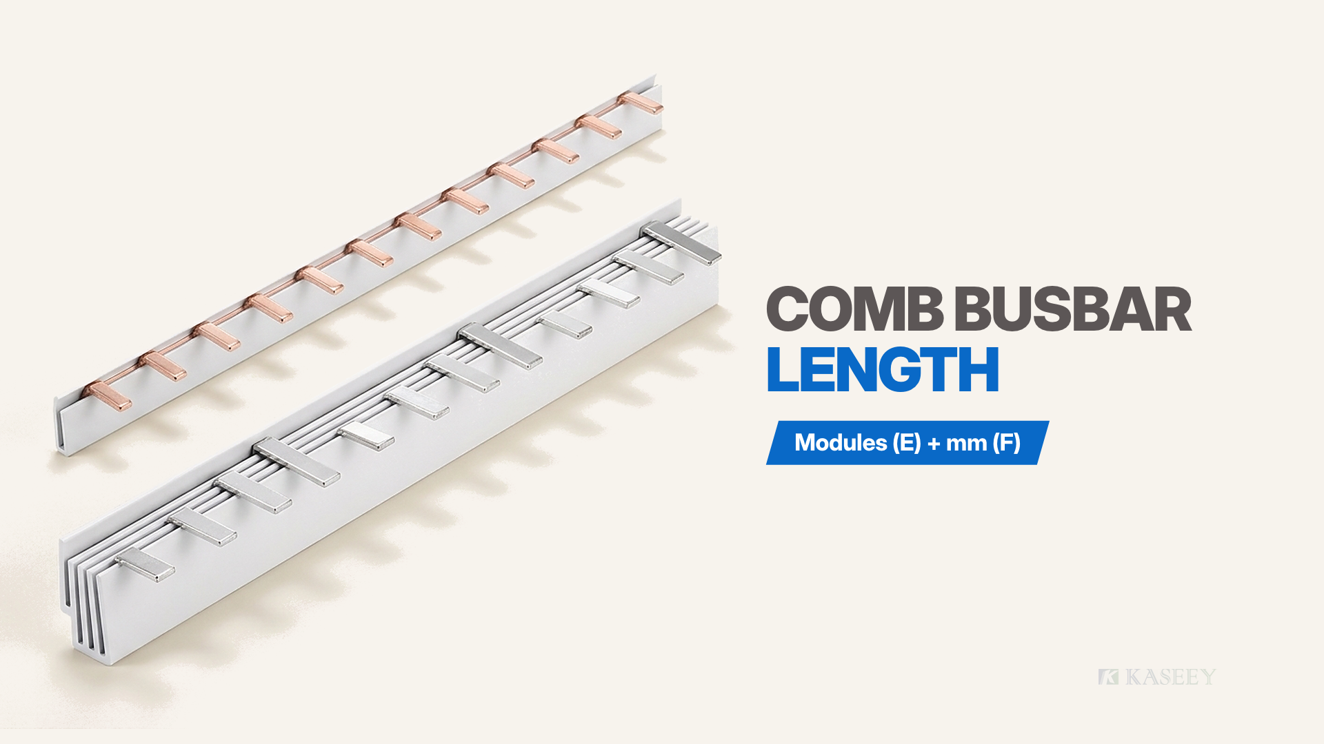
A comb busbar length is defined by two paired catalogue fields rather than one standalone dimension: module count (E), which counts usable tooth positions, and finished length (F), which states nominal overall bar length in millimetres. Because end insulation and housing geometry vary across product families, buyers cannot calculate finished millimetres from module count or divide millimetre length by pitch. Specify the exact Article No. or quote module count and finished millimetre length together from the target family’s published table. The pairing table in the next section shows how standard 210 mm, 1000 mm, and 1016 mm tiers map across three KASEEY comb busbar families.
Two Fields, One Specification
Every published KASEEY comb busbar specification pairs E (Modules) and F (Length in mm) as one indivisible dimensional identity. Module count establishes how many modular device terminal positions the copper comb feeds, while finished length records the nominal end-to-end physical length of the manufactured bar assembly.
Reading each column for its exact physical role prevents mismatches between panel layout drawings and purchasing schedules:
- Module count (E) counts tooth positions: Across KASEEY modular comb busbar series, the nominal device spacing (pitch) baseline is 17.8 mm, where 1 module equals 1 tooth position along the rail. For how tooth spacing itself is defined and verified on modular devices, see the MCB busbar pitch guide.
- Finished length (F) states overall bar millimetres: Column F records the published nominal overall length of the finished bar in millimetres, encompassing both the span across the copper teeth and the series-specific end-insulation overhang at both ends.
On KASEEY product pages—such as the published order matrix for P-1L pin-type 1-phase busbars—module count and finished length appear side by side on every row. Comparing three published KASEEY families shows these exact published pairings:
| KASEEY Product Family | Connection & Phase Configuration | Device Pitch (B) | Published Module Counts (E) | Published Finished Lengths (F) | Cross-Section & Reference Current |
|---|---|---|---|---|---|
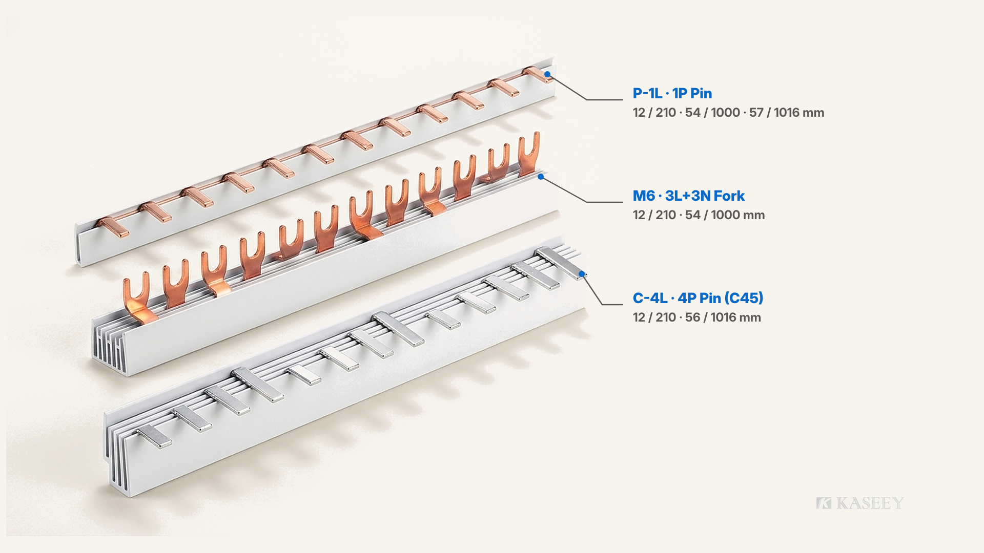
| P-1L | Pin-type, 1-phase | 17.8 mm | 12 / 54 / 57 | 210 / 1000 / 1016 mm | 8–16 mm²; 50–80 A |
| Fork-type 3L+3N (M6) | Fork-type, 3L+3N (M6) | 17.8 mm | 12 / 54 | 210 / 1000 mm | Published per M6 matrix |
| C-4L (C45 series) | Pin-type, 4-phase (C45) | 17.8 mm | 12 / 56 | 210 / 1016 mm | Published per C45 matrix |
Read E (Modules) and F (Length) strictly as a matched pair from the row of your target product family; never transfer a module-to-millimetre pairing from one comb busbar series to another.
Why Multiplying Modules by 17.8 mm Never Gives the Ordering Length
Buyers occasionally attempt to calculate comb busbar length by multiplying tooth count by the 17.8 mm pitch baseline. Comparing those arithmetic products against KASEEY’s published F column shows why manual conversion fails across every tier:
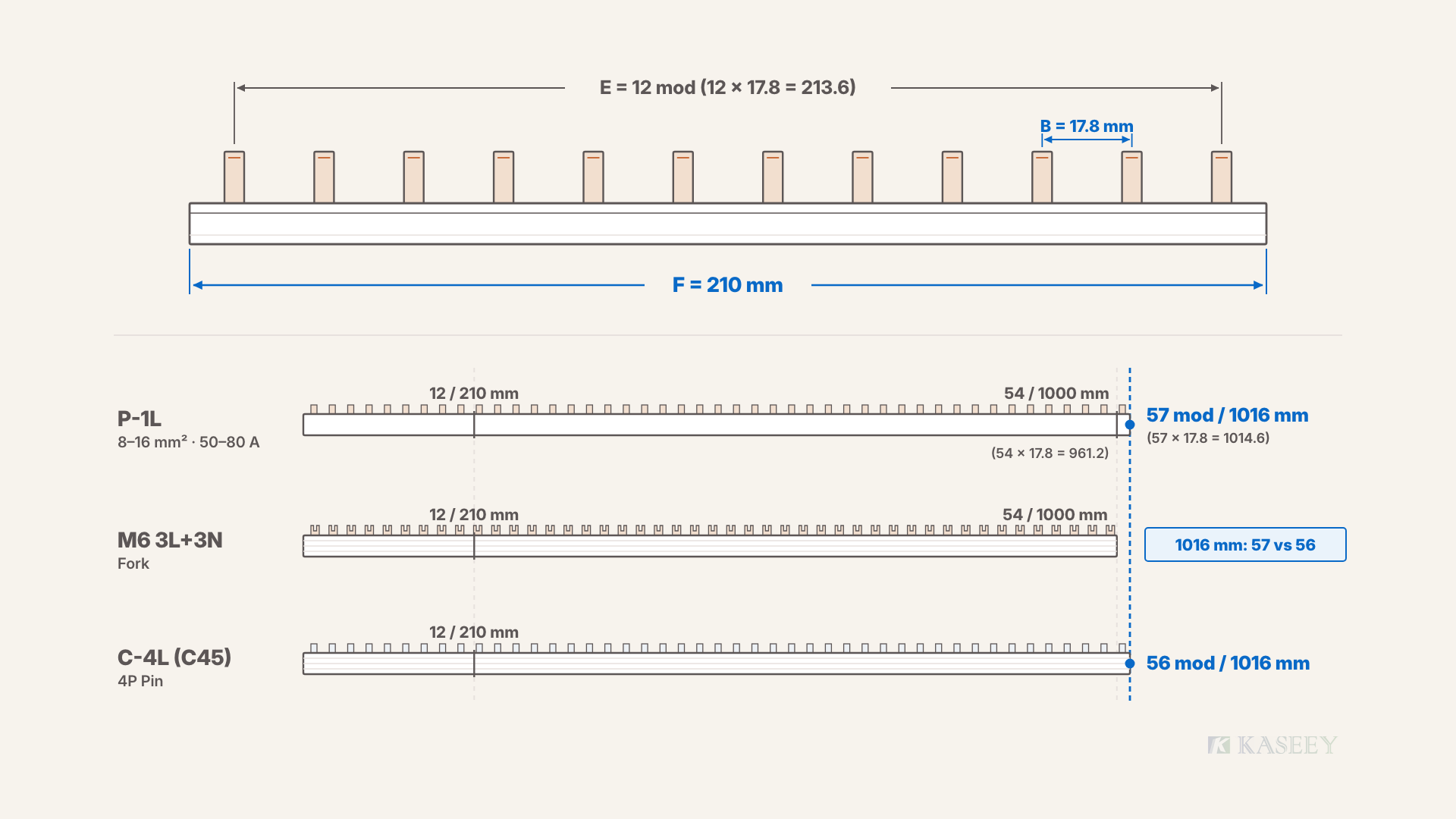
- 12 × 17.8 = 213.6 — whereas the published finished length of 12-module bars across all three families is 210 mm.
- 54 × 17.8 = 961.2 — whereas the published finished length of 54-module bars in both P-1L and fork-type 3L+3N (M6) is 1000 mm.
- 57 × 17.8 = 1014.6 — whereas the published finished length of the 57-module P-1L bar is 1016 mm.
Tooth pitch is a center-to-center spacing interval between adjacent contacts, whereas finished bar length reflects contact span plus end-insulation overhang. Writing 213.6 mm, 961.2 mm, or 1014.6 mm onto a purchase order cites theoretical pitch multiples that match zero catalogue items. Arithmetic explains why E and F differ; never treat it as an ordering formula.
Proof That Pairing Varies by Family: 1016 mm in P-1L vs C-4L
The decisive proof that comb busbar length cannot be converted without a family table sits directly in the 1016 mm tier: the identical 1016 mm finished length pairs with 57 modules in the P-1L family and pairs with 56 modules in the C-4L family.
Consider both failure modes when one half of the specification is omitted:
- Quoting millimetres alone (“1016 mm comb busbar”): In P-1L (pin-type, 1-phase), 1016 mm provides 57 tooth positions. In C-4L (pin-type, 4-phase, C45), 1016 mm provides 56 tooth positions. Describing 1016 mm bars loosely as an approximate range masks a real physical difference of one tooth position—enough to leave the final pole on a C45 row unfed.
- Quoting module count alone (“54-module or 57-module bar”): P-1L and fork-type 3L+3N (M6) publish 54 modules paired with 1000 mm, whereas C-4L publishes no 54-module or 1000 mm row—its long standard bar is 56 modules paired with 1016 mm, and neither fork-type 3L+3N (M6) nor C-4L publishes a 57-module standard bar.
Single-phase channels, multi-layer 4-phase C45 extrusions, and M6 fork housings use distinct end structures. Always read module count and millimetre length together from the target series table.
Count the Modules Your Row Needs
To find the module count required for a DIN-rail device row, add the modular pole widths of every device fed by that continuous comb busbar. At the 17.8 mm pitch baseline, each standard modular pole width occupies 1 module (1 tooth position on the busbar).
Apply the pole-footprint counting weights below solely to total the required busbar tooth positions along your row:
| Device Pole Footprint on the Rail | Module Count per Device | Row Summation Rule |
|---|---|---|
| 1P device | 1 module | Device quantity × 1 |
| 1P+N two-module device | 2 modules | Device quantity × 2 |
| 3P device | 3 modules | Device quantity × 3 |
| 3P+N or 4P device | 4 modules | Device quantity × 4 |
Calculate the exact integer sum of busbar-fed modules across the continuous rail first, then check whether your target KASEEY busbar family publishes that module count as a standard row.
Two Row Counting Examples
Two common panel-row calculations illustrate what happens when a row matches a published tier versus when it lands between standard sizes:
- Example (a) — 12 single-pole MCBs: Twelve 1P MCBs mounted side by side require 12 × 1 = 12 modules. Checking Section Two’s pairing table shows that 12 modules corresponds directly to the 210 mm standard bar published in P-1L (as well as fork-type 3L+3N M6 and C-4L for matching device layouts). The standard 12-module / 210 mm bar fits the row directly.
- Example (b) — 9 two-module 1P+N RCBOs: Nine 1P+N RCBOs occupy 2 modules each, giving 9 × 2 = 18 modules. Checking the published tables for P-1L (12 / 54 / 57 modules), fork-type 3L+3N M6 (12 / 54 modules), and C-4L (12 / 56 modules) confirms that none of these product families publishes an 18-module standard bar.
When a row total such as 18 modules does not exist as a standard published bar, never invent an estimated millimetre figure on an RFQ. Only two valid routes exist: cut sections from a published 1-meter-class bar (1000 mm or 1016 mm depending on the family), or request a factory custom length for repeat panel production.
Standard Lengths and When Each Makes Sense
Published KASEEY comb busbar matrices organize stock bars into a 210 mm short tier and a 1-meter-class (1000 mm or 1016 mm) long tier, supplemented by factory custom lengths for recurring OEM rows. Choosing the right tier depends on whether your row equals 12 modules, varies by project, or repeats across serial builds.
| Sourcing Tier | Published KASEEY Pairings | Primary Panel Application | Selection Judgment |
|---|---|---|---|
| 210 mm tier | 12 modules / 210 mm (P-1L, Fork 3L+3N M6, C-4L) | Compact 12-module sub-boards and fixed device groups | Mount straight from the carton when the row needs 12 modules. |
| 1-meter tier (1000 or 1016 mm) | 54 modules / 1000 mm (P-1L, Fork 3L+3N M6); 57 modules / 1016 mm (P-1L); 56 modules / 1016 mm (C-4L) | Full-width rows or shop stock cut to intermediate counts | Stock for long rails or cut down for intermediate rows like 18 modules. |
| Factory custom length | Built to confirmed project module count and length | Standardized OEM panels with recurring non-standard rows | Order when identical non-standard rows repeat across production batches. |
Use 210 mm bars for exact 12-module rows, select the target family’s published 1000 mm or 1016 mm bar for long rails or panel-shop stock, and reserve factory custom lengths for repeatable OEM assemblies:
- 210 mm tier (12 modules): Specify 210 mm bars whenever a compact distribution row totals 12 modules so installers mount factory-finished bars without shop modification.
- 1-meter tier (1000 mm or 1016 mm): Specify the exact 1000 mm (54 modules) or 1016 mm (57 modules in P-1L; 56 modules in C-4L) row listed for your target family when populating long rails or cutting stock for intermediate counts; cutting itself follows a dedicated process covered in how to cut a comb busbar.
- Factory custom length: Specify factory custom lengths when identical non-standard rows such as 18-module boards repeat across OEM production runs, reviewing available series baselines in the KASEEY comb busbars range.
Specify It in the RFQ
A complete comb busbar length specification removes all guesswork between buyer, sales engineer, and incoming quality control by locking both the catalogue identifier and the paired physical fields on one line. State all five items below whenever requesting a quote or issuing a purchase order.
| RFQ Item | Required Entry on the Order Line | Mistake Prevented |
|---|---|---|
| Product family & Article No. | Series code (P-1L, Fork 3L+3N M6, or C-4L) and published Article No. | Cross-family mix-ups between standard pin, M6 fork, and C45 |
| Module count (E) | Published tooth count (12, 54, 56, or 57, or custom row count) | Missing contact positions along the breaker row |
| Finished length (F) | Published mm length paired with E (210, 1000, or 1016 mm) | Manual pitch-conversion figures and 1000 vs 1016 mm errors |
| Pin or fork contact type | Pin-type or fork-type matching device terminals | Incompatible terminal contact geometry at assembly |
| Conductor cross-section | Published copper cross-section in mm² (such as 8–16 mm² on P-1L) | Ambiguous Article No. selection within a length tier |
Quote the published Article No. together with E (Modules), F (Length in mm), contact type, and cross-section from the same matrix row; for non-standard custom rows such as 18 modules, state the required module count and target series explicitly rather than inventing an unpublished catalogue length.
Finally, include one essential accessory check whenever ordering 1000 mm or 1016 mm bars to cut down in the panel shop: order matching insulating end caps on the same RFQ as the cuttable comb busbars so cut bar sections never wait on missing end protection. Verify the correct cap profile for your busbar series in how to select busbar end caps.
Frequently Asked Questions
How long is a 57-module comb busbar?
There is no universal millimetre answer detached from the product family. In KASEEY’s P-1L pin-type 1-phase family, 57 modules pairs in the published matrix with a 1016 mm finished length. Changing the product family changes the published pairing—C-4L (C45 4-phase) pairs 56 modules with 1016 mm, while fork-type 3L+3N (M6) pairs 54 modules with 1000 mm—so always read the target family’s table.
Can I specify a comb busbar by length in mm only?
No. Specifying millimetres alone leaves the tooth count ambiguous across families: the same 1016 mm finished comb busbar length delivers 57 modules in P-1L but 56 modules in C-4L (C45). Always state the exact Article No. or quote module count (E) and finished length (F) together as a matched pair from that family’s published table.
Why is one family’s long bar 1000 mm and another’s 1016 mm?
Different comb busbar families use different insulator extrusions, multi-phase channel layouts, and end-insulation allowances, producing distinct nominal finished lengths such as 1000 mm (54 modules in P-1L and fork-type 3L+3N M6) and 1016 mm (57 modules in P-1L; 56 modules in C-4L). Both figures are published nominal catalogue lengths; order strictly from the target family’s matrix.
How many modules do I need for 12 single-pole MCBs?
Twelve single-pole (1P) MCBs require 12 modules (12 tooth positions at 1 module per 1P device), matching the 12-module / 210 mm standard bar tier across P-1L, fork-type 3L+3N (M6), and C-4L. If the row includes two-module 1P+N devices instead of 1P MCBs, count each 1P+N unit as 2 modules and recalculate the row total before ordering.
Does a longer comb busbar carry more current?
No. Comb busbar current rating is determined by conductor cross-section and feed-in arrangement, not by bar length or module count—for example, P-1L publishes the same 50–80 A reference current range across 8–16 mm² cross-sections regardless of whether the bar is 210 mm, 1000 mm, or 1016 mm long. See comb busbar current ratings for end feed and centre feed for current sizing rules.
Sources
- Pin Type 1-Phase Busbars (P-1L) — KASEEY. Published 17.8 mm device pitch, 8–16 mm² cross-section range, 50–80 A reference current range, and paired 12 / 54 / 57 module counts with 210 / 1000 / 1016 mm finished lengths.
- Pin Type 4-Phase Busbars (C45) — KASEEY. Published C-4L (C45 series) 17.8 mm device distance and paired 12 / 56 module counts with 210 / 1016 mm finished lengths.
- Fork Type 3L+3N Busbars (M6) — KASEEY. Published M6 fork-type 3L+3N 17.8 mm device distance and paired 12 / 54 module counts with 210 / 1000 mm finished lengths.