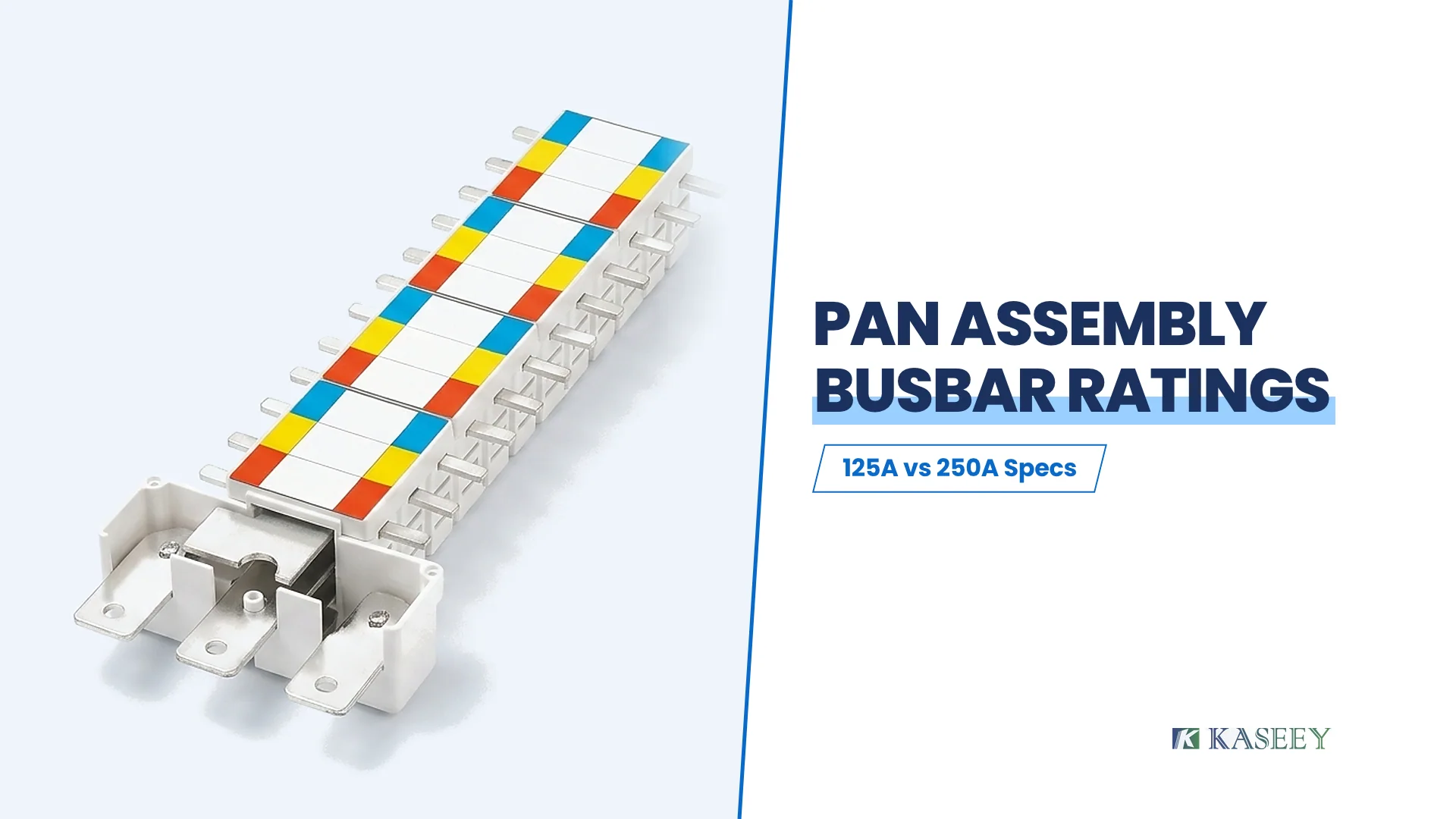
Pan assembly busbar ratings combine three separate engineering figures—nominal current class (such as 125 A or 250 A), outgoing branch terminal width and thickness (Connect size), and main phase-bar width and thickness (Outline size)—plus the insulated assembly envelope. Reading only the ampere label on a catalog line without checking terminal tab thickness and spine cross-section leads to cage-clamp fit failures or under-sized distribution interiors.
This technical reference explains how to interpret pan assembly busbar ratings on IEC low-voltage distribution boards governed by IEC 61439-1:2020 and IEC 61439-3:2024, using KASEEY’s published KP-125A and KP-250A specification tables as concrete hardware examples. Because KASEEY manufactures passive pan assembly busbar interiors rather than circuit breakers or enclosures, every dimension below addresses conductor sizing, terminal mating geometry, and enclosure-level verification boundaries.
Decoding the Four Columns of a Pan Assembly Busbar Spec Table
A pan assembly busbar datasheet separates electrical class from mechanical fit across four core columns: model code with way count, Connect size, Outline size, and Busbar size. Treating those four fields as a single dimensional set ensures that both the outgoing branch breaker jaws and the enclosure mounting chassis match the busbar before tooling or procurement begins.
On KASEEY’s live KP-125A and KP-250A pan assembly busbar page, every ordering row lists four structured specifications:
| Specification Column | Example (KP-125A / 24W) | Example (KP-250A / 24W) | What Physical Feature It Measures | Why Panel Builders Check It |
|---|---|---|---|---|
| Order model & way count | KP-125A / 24W | KP-250A / 24W | Nominal assembly current class (125 A or 250 A) and total outgoing ways (12W to 60W) | Sets main feeder capacity and total branch-breaker poles across both sides of the spine |
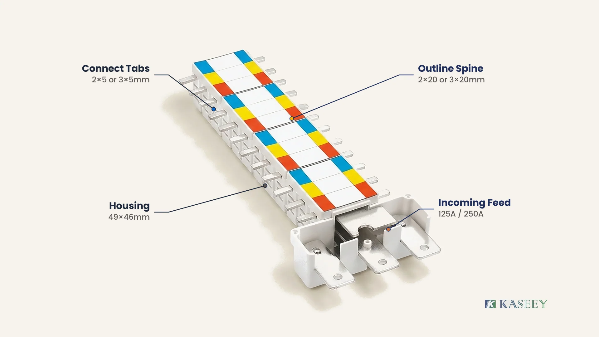
| Connect size (mm) | 2 × 5 mm (10 mm²) | 3 × 5 mm (15 mm²) | Thickness × width of each outgoing branch tap-off terminal tab | Governs mechanical fit inside outgoing MCB/RCBO cage-clamp jaws and branch thermal margin |
| Outline size (mm) | 2 × 20 mm (40 mm²) | 3 × 20 mm (60 mm²) | Thickness × width of each internal main phase copper spine | Governs main vertical current carrying capacity and heat dissipation inside the shroud |
| Busbar size (mm) | 288 × 49 × 46 mm | 288 × 49 × 46 mm | Overall length × width × height of the insulated pan assembly body | Governs backplate clearance, cover-plate cutout alignment, and enclosure depth |
Decision rule: Verify all four columns together before releasing a purchase order—match Connect size to the outgoing breaker’s terminal jaw drawing, Outline size to the main vertical current load, and Busbar size to the enclosure backplate layout.
Terminal Width vs Thickness: Why KP-125A and KP-250A Hold Width Constant
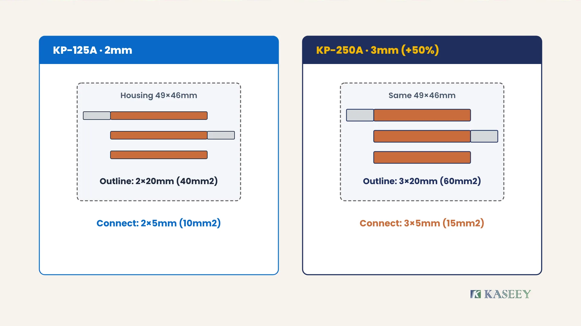
Between KASEEY’s KP-125A and KP-250A pan assembly busbars, conductor thickness increases by 50% (from 2 mm to 3 mm) while branch terminal width (5 mm), main spine width (20 mm), and housing dimensions (49 × 46 mm) stay constant. This raises tap-off area from 10 mm² to 15 mm² and main spine area from 40 mm² to 60 mm².
In flat busbar engineering, increasing width and increasing thickness do not have the same mechanical impact inside a compact distribution board, as detailed in KASEEY’s guide on copper busbar width vs thickness. Inside a pan assembly, two rigid physical boundaries dictate why manufacturers scale thickness instead of width:
- Outgoing breaker terminal slot width: Modular miniature circuit breakers (MCBs) and RCBOs have fixed horizontal terminal openings designed around standard 18 mm module pitches. Widening a branch tap-off tab beyond 5 mm risks colliding with the breaker’s molded plastic terminal barrier walls. Stepping thickness from 2 mm to 3 mm increases tap-off copper area by 50% without widening the tab.
- Shared insulated housing cross-section: Both KP-125A and KP-250A fit inside the same 49 mm wide × 46 mm high insulated body. Maintaining a 20 mm internal phase-bar width allows panel builders to upgrade a distribution board from 125 A to 250 A within the same chassis mounting footprint—provided the incoming feeder device, enclosure ventilation, and outgoing breaker jaws accommodate the thicker 3 mm conductor.
| Parameter | KP-125A Family | KP-250A Family | Engineering Change (125 A → 250 A) |
|---|---|---|---|
| Nominal current class | 125 A | 250 A | 2.0× nominal assembly class |
| Branch Connect size (thickness × width) | 2 × 5 mm | 3 × 5 mm | +1 mm thickness (+50% branch tab area: 10 → 15 mm²) |
| Main Outline size (thickness × width) | 2 × 20 mm | 3 × 20 mm | +1 mm thickness (+50% spine area: 40 → 60 mm²) |
| Insulated housing cross-section (W × H) | 49 × 46 mm | 49 × 46 mm | Identical enclosure mounting cross-section |
Decision rule: Select KP-125A (2 × 5 mm connect, 2 × 20 mm outline) for 125 A incoming panels where lighter breaker terminals are specified; step up to KP-250A (3 × 5 mm connect, 3 × 20 mm outline) when incoming capacity reaches 250 A, and always verify that the mating outgoing breaker’s cage-clamp jaw opens cleanly past 3 mm plus manufacturing tolerance.
Why a 50% Thicker Spine Supports a 125 A to 250 A Rating Step
A 50% thicker main spine (40 mm² to 60 mm²) supports stepping from 125 A to 250 A because multi-way pan assemblies do not carry 100% incoming current end-to-end. Outgoing breakers tap current progressively along both sides, and IEC 61439-1 / IEC 61439-3 govern actual ampacity through rated diversity factor (RDF) and enclosure temperature-rise limits.
Engineers reading pan assembly busbar ratings for the first time often compare 60 mm² (3 × 20 mm) against standalone flat copper bar tables in copper busbar current capacity guides and ask how a 3 × 20 mm bar sits inside a 250 A assembly. Three electrical and standards principles explain the relationship:
- Progressive current tapering along the spine: Full incoming current (InA) enters at the main incomer end and immediately splits across the first outgoing branch circuits. By the midpoint of a 24W or 36W pan assembly, the remaining spine carries only a fraction of the total incoming current, reducing aggregate I²R heating compared with a point-to-point feeder bar carrying 250 A end-to-end.
- IEC 61439-1 and IEC 61439-3 assembly ratings: Under IEC 61439-1:2020 and IEC 61439-3:2024 (published via the IEC Webstore), distribution boards operated by ordinary persons (DBOs) cover assembly rated currents (InA) up to 250 A and outgoing circuit ratings (Inc) up to 125 A. The assembly’s verified current rating depends on the rated diversity factor (RDF)—the per-unit loading expected across simultaneous outgoing circuits—and verified temperature-rise limits inside the actual enclosure.
- Thermal derating under continuous heavy loads: If a 250 A pan assembly supplies continuous high-duty loads (such as commercial EV chargers or heavy HVAC compressors) concentrated near the far end of the spine rather than distributed evenly, local heating rises sharply. In those architectures, panel builders must verify enclosure ambient temperature (typically 35°C average / 40°C peak under IEC 61439-1) and place highest-current branch circuits closest to the incoming feed end.
Way Count (12W to 60W) and Assembly Envelope Verification
Pan assembly busbar length scales directly with outgoing way count (12W through 60W), while housing width and height remain fixed at 49 × 46 mm across both KP-125A and KP-250A families. Checking exact published lengths alongside enclosure backplate clearance prevents late-stage sheet-metal rework during panel assembly.
Across KASEEY’s pan assembly busbar catalog, each standard 6-way increment (adding one 3-phase outgoing pair per side) increases overall length by 54 mm from 12W through 48W, with published lengths extending to 612 mm at 60W:
| Outgoing Way Count | KP-125A Order Model | KP-250A Order Model | Published Busbar Size (L × W × H) | Typical Panel Planning Note |
|---|---|---|---|---|
| 12W | KP-125A / 12W | KP-250A / 12W | 180 × 49 × 46 mm | Compact sub-distribution board |
| 18W | KP-125A / 18W | KP-250A / 18W | 234 × 49 × 46 mm | +54 mm per 6W step |
| 24W | KP-125A / 24W | KP-250A / 24W | 288 × 49 × 46 mm | Mid-size commercial 3-phase board |
| 30W | KP-125A / 30W | KP-250A / 30W | 342 × 49 × 46 mm | +54 mm per 6W step |
| 36W | KP-125A / 36W | KP-250A / 36W | 396 × 49 × 46 mm | High-density lighting and power board |
| 42W | KP-125A / 42W | KP-250A / 42W | 450 × 49 × 46 mm | +54 mm per 6W step |
| 48W | KP-125A / 48W | KP-250A / 48W | 504 × 49 × 46 mm | Large commercial floor distribution |
| 54W | KP-125A / 54W | KP-250A / 54W | 588 × 49 × 46 mm | Confirm exact mounting pitch on drawing before punching |
| 60W | KP-125A / 60W | KP-250A / 60W | 612 × 49 × 46 mm | Maximum standard way count; verify top/bottom cable bend radius |
Decision rule: Lock in the required way count (including spare ways for future expansion) and verify both the published assembly length and incoming-breaker cable bending space on the controlled mechanical drawing before finalizing enclosure height.
If you are still deciding whether your distribution board should use a pan assembly spine or modular DIN-rail comb busbars, review KASEEY’s pan assembly busbar vs comb busbar architecture guide. For complete nine-input panel layout and RFQ preparation, see KASEEY’s pan assembly busbar design guide and panel and pan assembly distribution solutions.
Five Checks Before Approving a Pan Assembly Busbar Rating
Translating catalog pan assembly busbar ratings into a compliant, field-ready switchboard requires five mechanical and thermal verification checks before ordering. Separating component nameplate figures (125 A or 250 A) from complete enclosed assembly qualification under IEC 61439-1 and IEC 61439-3 prevents terminal clamping mismatches, localized spine heating, and fault-withstand errors:
- Mating breaker jaw opening vs Connect thickness: Confirm the outgoing breaker datasheet accepts a 2 mm tab (KP-125A) or 3 mm tab (KP-250A) with full screw-thread engagement and rated clamping torque.
- Branch circuit concentration near the incomer: Place the highest-current outgoing breakers closest to the main incoming blades so heavy branch currents exit immediately instead of heating the full length of the 20 mm spine.
- Incoming feeder termination match: Verify whether the main incomer (MCCB, switch-disconnector, or incoming terminal block) bolts directly to the pan assembly’s incoming phase blades or requires copper link kits.
- Enclosure ambient and temperature-rise verification: Remember that a 125 A or 250 A pan assembly component rating does not replace IEC 61439-1 / IEC 61439-3 temperature-rise verification of the complete enclosed board with its actual IP degree and internal heat dissipation.
- Short-circuit withstand and neutral/earth coordination: Confirm the pan assembly’s insulated support spacing and upstream short-circuit limiting device (Icc) match the prospective fault level at the board’s installation point, alongside properly sized separate N and PE brass/copper bars.
Frequently Asked Questions
Does a 250 A pan assembly busbar mean every branch tap-off can carry 250 A?
No. The 250 A figure on a KP-250A pan assembly is the nominal main assembly incoming class, whereas each individual outgoing branch tap-off tab (3 × 5 mm, 15 mm²) feeds a single outgoing modular breaker pole (typically capped at ≤ 63 A or ≤ 125 A under IEC 61439-3 depending on breaker rating and terminal verification).
Will a 3 × 5 mm KP-250A terminal tab fit the same MCB terminal as a 2 × 5 mm KP-125A tab?
Not automatically. Although both tabs share the same 5 mm width to clear modular slot barriers, the KP-250A tab is 1 mm thicker (3 mm vs 2 mm). Always check the mating MCB or RCBO’s published cage-clamp opening height and busbar compatibility note before substituting a 250 A pan assembly into an existing breaker platform.
How does IEC 61439-3 apply to 125 A and 250 A pan assembly busbars?
IEC 61439-3:2024 covers enclosed distribution boards operated by ordinary persons (DBOs) with outgoing circuit ratings up to 125 A and assembly rated currents up to 250 A. A pan assembly busbar supplies the internal conductor spine, while full IEC 61439-3 compliance is verified on the complete assembly—enclosure, incoming device, outgoing breakers, diversity factor, and temperature rise.
Requesting Controlled Drawings for KP-125A and KP-250A Pan Assemblies
Before punching enclosure backplates or freezing a distribution board BOM, request the controlled dimensional drawing for your exact way count (12W to 60W), current class (KP-125A or KP-250A), incoming link arrangement, and destination standard. Contact KASEEY’s engineering team or email [email protected] with your single-line diagram, target outgoing breaker model, and enclosure constraints to confirm exact terminal fit and assembly specifications.
Sources
- IEC Webstore — IEC 61439-1:2020 and IEC 61439-3:2024 — International Electrotechnical Commission (IEC); official standards catalogue defining general rules (IEC 61439-1:2020: assembly rated current InA, rated diversity factor RDF, temperature-rise verification) and distribution boards operated by ordinary persons (IEC 61439-3:2024: Inc ≤ 125 A, InA ≤ 250 A).
- Pan Assembly Busbars KP-125A and KP-250A | KASEEY — KASEEY; live first-party product specification table documenting KP-125A (2 × 5 mm connect, 2 × 20 mm outline) and KP-250A (3 × 5 mm connect, 3 × 20 mm outline) across 12W to 60W and 180 to 612 × 49 × 46 mm assembly envelopes.
- Pan Assembly Busbars | KASEEY — KASEEY; product category hub for multi-pole distribution board pan assembly busbar interiors.
- Panel & Pan Assembly Distribution | KASEEY — KASEEY; solution overview covering pan assembly busbars, solid copper bars, and enclosed distribution hardware.