Investigate a pan assembly busbar when the project needs a coordinated distribution interior with incoming, outgoing, mounting and protective-cover interfaces. Investigate a comb busbar when the task is to connect an identified row of modular devices through their permitted busbar terminals. The useful choice starts with the panel layout and its interfaces, then moves to a documented product configuration.
Current and phase count belong in that review, but neither creates a universal dividing line. A three-phase panel can use a suitable multi-phase comb busbar; a pan assembly’s current-class name does not establish the rating of the completed panel. Likewise, matching the number of circuits does not make the two products interchangeable.
This guide provides a conditional architecture decision for engineers and technical buyers. Its output is a candidate route and the evidence needed to confirm it. Detailed dimensions, device compatibility and final assembly approval follow from the selected model, controlled drawings and project review.
Compare the distribution role before comparing products
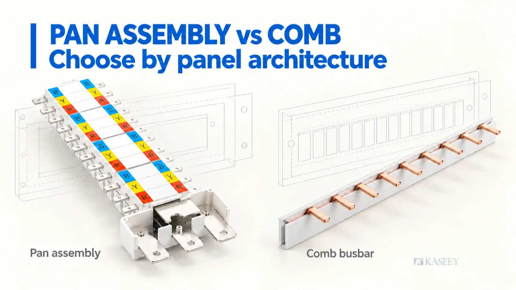
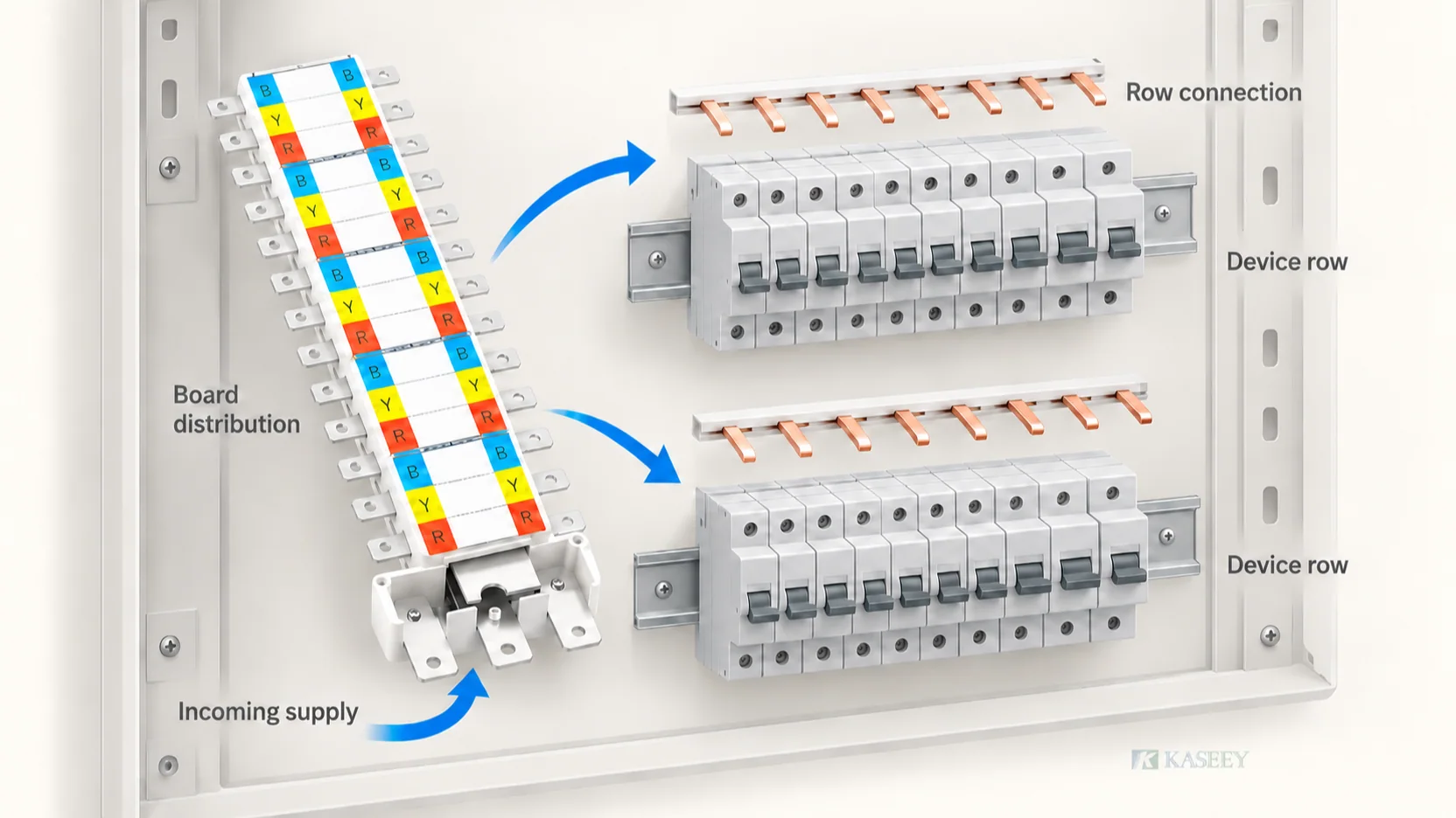
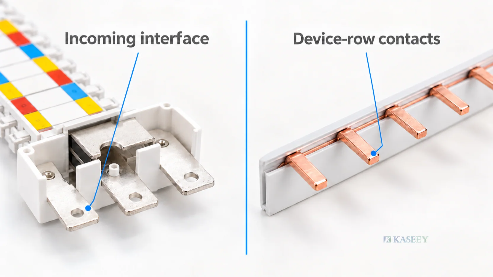
The KASEEY pan assembly range is organized around panelboard and distribution-board interiors. The pictured assembly brings incoming and repeated outgoing connection areas together with identification, support and shrouding features. Its position relative to the outgoing devices, mounting surface and enclosure is part of the selection.
The KASEEY comb busbar range offers pin, fork and custom configurations for compatible modular-device terminals. Here, the device row establishes the contact geometry, pitch and conductor sequence that the busbar must follow. Feed connectors, end treatment and protection for unused contacts complete the chosen arrangement.
The mechanical distinction needs care: the modular devices may mount on a DIN rail, while the comb connects to their terminals. Do not assume that a loose comb busbar itself clips to the rail, or that DIN mounting proves its contacts fit every device.
Other manufacturers make the same architecture distinction. Schneider Electric’s chassis and comb overview describes a board chassis as a mounting and distribution framework and comb busbars as typically used in DIN-row installations. Its named ranges include different phase arrangements. Those examples clarify the roles; their ratings and compatible devices do not transfer to a KASEEY configuration.
Give both candidates the same project brief
Compare the options against one requirement package. If the pan proposal and comb proposal assume different loads, incoming devices or enclosure space, their apparent advantages may come from different assumptions.
Record these inputs before selecting a route:
- Electrical function: single-line diagram, supply arrangement, design duty, phase assignment, neutral and protective-earth arrangement, and required protection or separation.
- Incoming interface: exact incomer or feed reference, connection arrangement, conductor approach and required access.
- Outgoing schedule: exact device models, poles, physical order, auxiliaries, spare positions and circuit allocation.
- Mechanical layout: mounting surface or device rails, reference positions, available enclosure space, wiring zones and front-cover line.
- Evidence: destination market, applicable assembly framework, controlled drawings and required product or assembly records.
A single-line diagram describes electrical function. It does not by itself establish terminal alignment, mounting holes, shroud fit or cable space. Pair it with a physical arrangement drawing so the same circuit schedule can be assessed against both candidate architectures.
Use this architecture decision table
Read each row as a condition to investigate, then close its evidence question. A candidate that fits the first row can still fail at the incoming connection, outgoing terminal or enclosure interface.
| Project question | Investigate a comb route when… | Investigate a pan route when… | Confirm before selection |
|---|---|---|---|
| What must the busbar organize? | The task is to connect a defined modular-device row. | The task is to coordinate incoming distribution, repeated outgoing positions and the supporting interior. | Which distribution stage and physical interfaces the selected component covers. |
| How does the supply enter? | A documented row feed connector or device connection serves the chosen arrangement. | A defined pan incoming zone can be coordinated with the incomer, conductors or links. | Exact feed components, connection geometry, conductor approach and access. |
| How are outgoing devices allocated? | Terminal positions, device widths and conductor sequence can be matched across the row. | The outgoing-device platform can be allocated to the pan’s documented positions. | Device references, pole allocation, auxiliaries, spares and terminal engagement. |
| What defines the mounting plane? | The mounted device row supplies a stable reference for contact alignment. | The pan supports and mounting pattern establish the interior’s position relative to devices and covers. | Mounting references, controlled offsets and the complete mechanical arrangement. |
| Does the arrangement fit the enclosure? | The complete row, feed, end accessories and wiring envelope fit the available space. | The pan, incoming zone, outgoing devices, supports and cover envelope fit together. | Wiring space, front-cover line, door clearance and service access. |
| How are neutral, earth and protection handled? | The documented row arrangement and accessories meet the required conductor and protection scheme. | The defined interior can be coordinated with the required neutral/earth elements, barriers and covers. | Circuit functions and the completed protection arrangement; appearance alone proves neither. |
| What supports the required duty? | Exact comb, devices and feed conditions have suitable evidence for the application. | Exact pan configuration and completed interior have suitable evidence for the application. | Model scope, installed conditions and the relevant assembly verification. |
Do not use the table as a scoring contest. An unresolved essential interface remains a confirmation point even when the candidate appears to satisfy the other rows.
When the comb route is a useful starting point
A comb route is worth investigating when the device lineup is already defined and its terminals support a documented row connection. The task is then to reproduce that contact pattern, conductor sequence and feed arrangement within the available panel space.
Check the complete lineup. An RCCB, RCBO, auxiliary or wider device can interrupt a pattern that works across identical MCBs. A matching nominal module width is therefore insufficient. ABB’s modular busbar guidance identifies terminal type, poles, device type, combinations and modules as separate selection inputs.
Once that architecture is appropriate, use the MCB busbar selection guide to determine the exact interface, pitch, sequence, electrical evidence, finished length and accessories. This comparison does not replace that model-selection work.
Specify the feed point and end condition with the busbar. Do not assume every family allows either-end feeding, centre feeding, cutting or the same protective accessories. Confirm those details for the proposed reference before treating the row as an approved arrangement.
When the pan route is a useful starting point
A pan route is worth investigating when a defined incoming and outgoing distribution interior can be coordinated with the proposed device platform and enclosure. The main question is whether its connection positions, supports, incoming zone and protection arrangement fit the whole interior.
KASEEY’s pan assembly product page publishes KP-125A and KP-250A current classes with 12W–60W configuration references. These are starting points for product review. The W identifier is not proof that the assembly accepts that many outgoing circuits in every pole arrangement, and a class name is not the finished cabinet rating.
Map every proposed outgoing device to physical positions on the controlled arrangement. A multi-pole device, auxiliary or reserved space changes that allocation. Then check the incoming approach, mounting pattern, device position and cover line together. Published product length, width and height do not include every installation allowance.
Use the pan assembly design guide for the deeper KP configuration, incomer, enclosure and verification review. A pan that fits inside the cabinet outline can still leave inadequate connection or service space, or place outgoing tabs incorrectly relative to the device terminals.
Keep the performance review attached to the complete arrangement
Either route needs evidence for its actual duty. Review the supply and fault context, connected devices, feed arrangement, conductor requirements and installed conditions. A product photograph, conductor area or familiar model name cannot replace that evidence.
For projects using the IEC 61439 framework, IEC TR 61439-0:2022 supports defining assembly functions and interface characteristics from the specifier’s requirements. IEC 61439-1:2020 provides general assembly requirements used with the relevant assembly part. Selecting a loose busbar or interior does not complete that assembly verification.
Keep product documents and assembly conclusions distinct. Confirm what the exact model’s report covers, and what remains to be established for the devices, enclosure and configuration used in the project. Do not transfer another manufacturer’s board certification or a different KASEEY model’s rating to the proposed arrangement.
A panel can contain more than one distribution stage
Consider a conceptual project in which a board interior distributes the incoming supply to outgoing feeders, and one feeder serves a separate DIN-mounted control-device row. A reviewed pan interior could be a candidate for the board stage, while a compatible comb could distribute supply across the defined modular row.
This is a functional example, not a recommendation to connect a comb directly to a pan tab. The project engineer must define the feeder, protective devices, conductors, terminations, neutral/earth scheme and verification for each stage and their connection. Each component retains its own documented interface and operating conditions.
The example shows why the question is sometimes “which architecture serves this distribution stage?” rather than one product choice for the entire cabinet. If the approved platform uses another arrangement, follow that platform’s documented construction.
Reopen the decision when its assumptions change
Reassess the candidate route when an exact device family changes, an auxiliary moves a terminal position, or the outgoing pole/neutral allocation changes. A substitution with the same nominal current can still alter the physical interface.
Changes to the incomer, feed location, conductor approach, mounting plane, cabinet dimensions or front-cover opening also need review. So do revised duty, fault requirements, installation conditions or destination-market documentation. Retain the original comparison record so the affected assumption can be identified.
For a retrofit, start from the existing approved arrangement and its condition. Replacing a pan with combs, or combs with a pan, can change support, wiring, protection and service interfaces. Treat that as an architecture review, not a parts substitution justified by appearance.
If drawings conflict, a necessary interface is undocumented or the proposed device combination is unsupported, keep the choice open. Request the relevant controlled reference or agree a reviewed sample assessment before releasing a production specification.
Record the candidate route and next approval step
Use a short decision record that engineering and purchasing can retrieve on the next review. Blank fields below are entries for the project team; they do not imply that a particular configuration has already passed.
| Decision field | Project entry |
|---|---|
| Panel, distribution stage and market | ___ |
| Single-line, load schedule and arrangement drawing revisions | ___ |
| Incoming and outgoing device references | ___ |
| Candidate route and reason | Pan / comb / further review: ___ |
| Busbar reference and interface documents | ___ |
| Mounting, enclosure, neutral/earth and protection scope | ___ |
| Required performance and verification evidence | ___ |
| Open confirmations, responsible owner and next review | ___ |
| Decision scope, reviewer and date | ___ |
Send this record with the device schedule, drawings, quantity and destination market when requesting a KASEEY review. Include the incoming connection, available assembly space and required accessories. Contact KASEEY to identify the applicable model documents and next sample or interface-review step. Carry the agreed drawing and configuration reference into the subsequent detailed selection and supply approval.