Short Answer
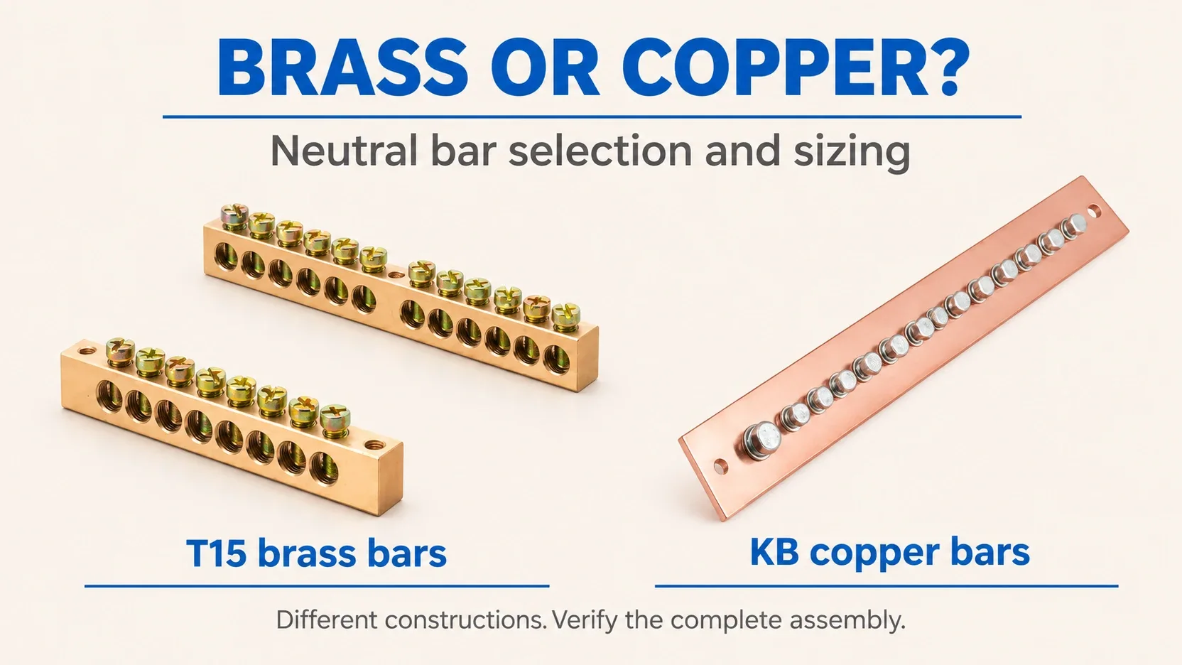
For most ordinary distribution-board neutral-bar selections, start with brass: an appropriately rated brass terminal bar is often sufficient and can be the more economical finished-part choice. This is a selection starting point, not a claim that every brass bar suits every board. Choose copper when the available brass assembly cannot meet the required neutral current, temperature-rise or loss limit within the available space, or when the approved panel specification requires copper. High harmonic loading and sustained heavy neutral current make copper worth evaluating early; they do not automatically prohibit brass.
Size the neutral current first, then verify the complete bar and its terminations. Neither the number of holes nor a conductivity ratio establishes an ampere rating.
The practical brass neutral bar vs copper neutral bar decision is about the return-current path in a particular board. This guide takes you from load assumptions to a documented candidate, using Kaseey’s published dimensions without inventing missing electrical ratings.
For neutral/earth function separation and the existing T15 purchasing checklist, see Brass Bars for Neutral and Earth Distribution. The broader panel-material discussion belongs in Copper Bars vs Brass Bars for Electrical Panels.
Material data: what 28% IACS actually means
IACS expresses conductivity relative to the International Annealed Copper Standard. “Brass is approximately 28% IACS” is a useful example only when the alloy is named. The Copper Development Association (CDA) lists C26000 cartridge brass at 28% IACS, while C36000 free-cutting brass is 26% IACS. Its C11000 copper record lists 101% IACS and a minimum of 100% in the annealed condition.
| Material reference | Conductivity at 20 C | Use in this neutral-bar comparison | Source |
|---|---|---|---|
| C26000 cartridge brass | 28% IACS | Example for the 28% calculation | CDA C26000 record |
| C36000 free-cutting brass | 26% IACS | Shows why the brass grade changes the result | CDA C36000 record |
| C11000 ETP copper | 101% IACS listed; 100% minimum when annealed | Named high-conductivity copper reference | CDA C11000 record |
| Kaseey T15 brass bar or KB copper bar | check the datasheet | Confirm the actual supplied grade and temper | Kaseey product records below do not declare these CDA grades |
These are material-reference values, not measured conductivity or current ratings for Kaseey products. Do not assign C26000, C36000 or C11000 to a purchase order without the manufacturer’s material confirmation.
Calculate an equal-resistance section, not a current rating
For a uniform solid conductor:
R = L / (sigma x A)
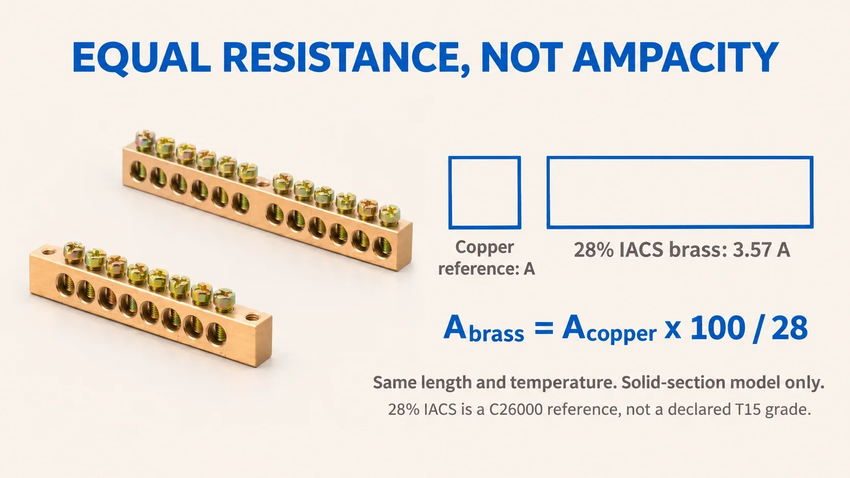
Here, L is current-path length, sigma is conductivity and A is cross-sectional area. At the same current, resistive power loss is P = I^2 x R. Holding length, temperature and resistance constant gives:
A_brass / A_copper = sigma_copper / sigma_brass
Using a 100% IACS copper reference and 28% IACS brass:
A_brass = A_copper x 100 / 28 = 3.57 x A_copper
For an illustrative 25 mm2 solid copper section, the equal-resistance brass section is 25 x 100 / 28 = 89.3 mm2. Using the CDA’s listed 101% value instead gives 25 x 101 / 28 = 90.2 mm2. At 26% IACS, the 100% reference calculation becomes 25 x 100 / 26 = 96.2 mm2.
Those calculated areas are not approved neutral-bar sizes. Real terminal bars have drilled holes, changing current paths, connection resistance and heat-transfer conditions. Current also varies along a multi-way bar as individual circuits connect. Equal bulk resistance does not guarantee equal temperature rise or short-circuit performance.
For orientation only, a rectangular 6 x 9 mm envelope gives 54 mm2 gross area, and 8 x 12 mm gives 96 mm2. These are arithmetic products of the outer dimensions, before any holes. The proximity of 96 mm2 to a calculated result does not approve an 8 x 12 T15 bar for the same duty as a particular copper bar. The Copper for Busbars handbook, sections 2.2 and 6, explains why heat balance and joint design also matter.
How to Size a Neutral Bar
Step 1: establish the neutral design current
Write down the supply arrangement, simultaneous load demand, phase allocation, harmonic spectrum and expected operating duration. Use load data or measurements appropriate to the operating cases, including planned expansion. Do not simply add every outgoing breaker rating or assume a balanced three-phase board has no neutral load.
- Single-phase, two-wire loads: the neutral carries the circuit return current. For a single-phase board, assess the maximum simultaneous neutral demand through the common incoming connection and each bar segment.
- Three-phase imbalance: at the fundamental frequency, add the three phase-current phasors. For sinusoidal loads with equal displacement power factor,
I_N = sqrt(I_A^2 + I_B^2 + I_C^2 - I_A I_B - I_B I_C - I_C I_A). Different power factors require the actual phase angles. - Triplen harmonics: balanced third-harmonic components add in the neutral rather than cancelling. Under that assumption,
I_N,3 = 3 x I_phase,3. Combine different-frequency neutral components by root-sum-square. A harmonic-rich neutral can reach or exceed the phase-current level; inspect the spectrum rather than relying on phase balance.
This harmonic behaviour is addressed in IEC 60364-5-52 Amendment 1:2024, Annex E. Its cable factors are not neutral-bar ampacity factors.
Step 2: check whether neutral-conductor reduction is allowed
The correct reference is IEC 60364-5-52, Clause 524, not a separate “IEC 60364-5-524” standard. Amendment 1:2024 replaces 524.2:
- Single-phase circuits require a neutral section at least equal to the line section.
- The same applies to polyphase circuits with line sections up to 16 mm2 copper or 25 mm2 aluminium.
- In other cases, a reduced neutral must remain at least 16 mm2 copper or 25 mm2 aluminium, and at least 50% of the line section.
- With triplen harmonics, 524.3 directs selection to Annex E or consideration of IEC 60364-4-43:2023, 431.2.3.
These are conductor rules, not permission to halve a brass bar. Verify current-carrying capacity, overcurrent protection, installation conditions and the locally adopted edition. Do not reuse the unamended 2009 harmonic thresholds as the complete current rule. Read the IEC amendment text, Clauses 524.2 and 524.3.
Step 3: shortlist the profile against manufacturer evidence
Start with the Kaseey brass bar range and neutral and earth distribution product route. The table below extracts only the dimensional facts needed for a 12-outgoing-position comparison. It is not a repetition of the full T15 order matrix.
Evidence boundary: the public T15A / T15B technical table lists model, ways, profile and diameter. It does not publish an ampere rating, conductor acceptance range or tightening torque for these rows. Its controlled technical datasheet is available by request. Every missing selection field therefore remains check the datasheet.
| Selection field | T15A-0609/12+1 | T15A-0812/12+1 |
|---|---|---|
| Product family | T15A brass bar | T15A brass bar |
| Published profile, mm | 6 x 9 | 8 x 12 |
| Published ways | 12 | 12 |
| Published diameter, mm | 5.2 | 6.0 |
| Rated continuous current and reference conditions | check the datasheet | check the datasheet |
| Permitted conductor material, size and construction | check the datasheet | check the datasheet |
| Incoming-terminal acceptance and allocation | check the datasheet | check the datasheet |
| Tightening torque | check the datasheet | check the datasheet |
| Temperature-rise and enclosure conditions | check the datasheet | check the datasheet |
| Short-circuit duty and support arrangement | check the datasheet | check the datasheet |
The larger profile is a candidate when more conductive section or a different terminal geometry is needed. It is not automatically a higher approved current rating. A 6.0 mm hole also does not establish a 6 mm2 wire rating: diameter and conductor cross-sectional area are different quantities.
For a copper alternative, Kaseey’s KB Series product table publishes KB320125 as 3 x 20 x 125 mm and KB440180 as 4 x 40 x 180 mm. These are different copper-bar constructions, not interchangeable T15 neutral terminals. Their neutral-terminal configuration, approved conductor interfaces and installed current duty require confirmation; no current rating is inferred here.
Step 4: allocate ways and verify each connection
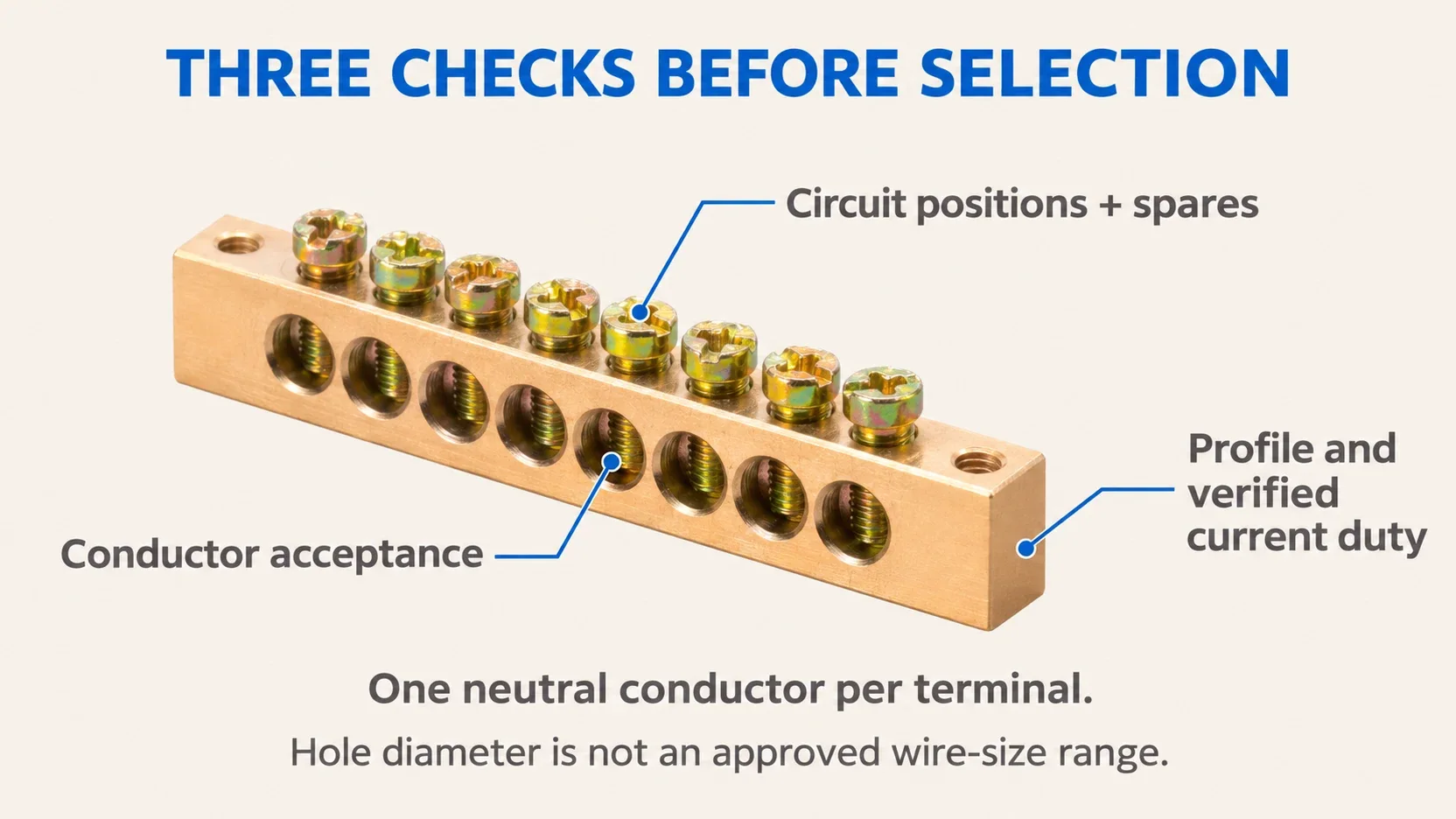
Count the outgoing neutral conductors, add the agreed spare positions, and provide a separately verified incoming connection. Use one neutral conductor per terminal for this selection workflow. Do not put two neutrals in one hole to avoid choosing a longer bar.
For example, ten outgoing neutrals plus two spares require twelve usable outgoing positions, in addition to the incoming termination. Confirm how the chosen drawing allocates them; do not assume the +1 or +2 suffix establishes incoming-wire capacity. Keep each protected circuit’s neutral on its designated path.
After counting positions, check conductor acceptance, preparation, torque, mounting, clearance and duty against the exact assembly documents. Spare holes provide expansion positions, not spare amperes. If the job actually requires a separately mounted terminal-block assembly, use the Brass Terminal Block Selection Guide; that is a different product-selection route.
Worked example: a single-phase board with ten outgoing neutrals
Assumptions, not Kaseey ratings: a designer has established a maximum simultaneous return demand of 32 A for a single-phase board; line and neutral feeder conductors are both 6 mm2 copper, with their installation suitability checked separately. Ten outgoing circuits each require one neutral terminal, and two future circuit positions are reserved. Outgoing conductors are assumed to be 2.5 mm2 copper. The intended enclosure ambient is 40 C, and full design demand may persist for several hours. These project inputs must be checked against the final load schedule.
| Selection step | Example result |
|---|---|
| Determine neutral demand | Use 32 A through the incoming neutral connection; do not discount it because the bar is labelled neutral. |
| Apply the neutral-conductor rule | Retain the full 6 mm2 neutral; the single-phase case does not use a reduced neutral. This does not specify the brass-bar section. |
| Count positions | 10 working positions + 2 spare outgoing positions, plus a documented incoming termination. |
| Use the product table | Shortlist T15A-0609/12+1. Keep T15A-0812/12+1 as the alternative profile to evaluate. Both have 12 published ways. |
| Check connections | Obtain explicit acceptance for the 6 mm2 incoming and 2.5 mm2 outgoing conductors, their construction and preparation. Neither 5.2 nor 6.0 mm hole diameter supplies this approval. |
| Close the thermal requirement | Require evidence covering at least the 32 A design duty at the specified installed conditions, including the 40 C enclosure environment and sustained loading. |
| Make the release decision | Neither row can be released from the public dimensions alone. Select the 6 x 9 candidate only if the controlled data confirms all requirements; otherwise evaluate the 8 x 12 assembly or a documented copper solution. |
The result is a specific, reviewable shortlist and a clear pass/fail requirement, not an invented “6 x 9 = 32 A” rule. If no candidate has adequate documentation, the correct outcome is to hold component approval. Spare positions also require a fresh load assessment before future circuits are connected.
For an assembly using the IEC 61439 framework, IEC 61439-1:2020 defines general construction and verification requirements together with the relevant assembly part. A material calculation does not complete that verification.
When copper is worth it, and when brass is enough
| Neutral duty or design constraint | Material decision | Evidence that settles it |
|---|---|---|
| Ordinary distribution board with moderate verified neutral demand | Brass is a sensible first candidate and may offer lower finished-part cost. | The exact brass assembly meets current, connection and temperature requirements. |
| Many single-phase electronic loads across three phases | Evaluate copper early if harmonics create heavy neutral loading. | Harmonic spectrum, maximum neutral RMS current and installed thermal assessment. |
| High neutral current in a compact enclosure | Copper’s lower bulk resistance can be valuable where a larger brass section will not fit. | Complete copper assembly fits and meets the specified duty. |
| Long periods near full neutral design load | Compare sustained losses and temperatures; copper may justify additional initial cost. | Equivalent-duty comparison, including joints, cooling and operating hours. |
| Brass candidate fails the permitted temperature rise or loss limit | Change the design. Copper is necessary if it is the approved solution that meets the constraints; a larger verified brass design may also work. | Verification for the revised assembly, not a same-size material swap. |
| Panel specification mandates copper | Use the specified copper assembly unless a formal design change is approved. | Approved panel specification and component documentation. |
The cost comparison is qualitative. Compare finished assemblies with equivalent connections, supports, inspection and duty; no raw-metal price or universal saving percentage establishes the cheaper approved solution.
Common neutral-bar sizing mistakes
- Selecting only by ways. Twelve available positions tell you where wires can terminate, not how much return current the assembly can carry.
- Replacing copper with brass at the same dimensions. At equal length and temperature, the illustrative 28% IACS brass has about 3.57 times the bulk resistance of a 100% IACS copper reference. Recheck the complete design instead of copying dimensions.
- Treating a gross profile as an uninterrupted conductor. The 54 or 96 mm2 outer-envelope arithmetic ignores holes, local current crowding and connections.
- Assuming phase balance eliminates neutral heating. Fundamental balance does not cancel balanced triplen harmonic components.
- Blaming all overheating on brass. A hot connection may involve poor contact pressure, unsuitable conductor preparation, overload, harmonics or enclosure conditions. A localized hot joint suggests a different investigation from heating spread along the bar; neither observation alone proves the cause. The busbar handbook’s joint guidance explains the importance of contact surfaces and pressure. Inspect de-energized equipment under the applicable safe-work procedure; do not substitute copper to conceal an unresolved connection problem.
- Treating a wire-reduction allowance as a bar rating. IEC wiring-conductor rules and the manufacturer’s terminal-bar verification answer different questions.
FAQ
Is brass or copper better for a neutral bar?
Brass is a practical starting point for an ordinary distribution board when the exact terminal-bar assembly meets its neutral-current and temperature requirements. Copper is attractive when high neutral current, sustained loading or limited space makes lower bulk resistance valuable. Neither material is automatically approved by its name; select the documented assembly for the actual duty.
How much larger must a brass neutral bar be than copper?
There is no universal approved size multiplier. For equal length, temperature and bulk resistance, a solid 28% IACS brass section needs about 3.57 times the area of a 100% IACS copper reference. That calculation does not rate a drilled neutral bar: alloy, holes, terminals, cooling and installed temperature limits still determine suitability.
Can a neutral bar be smaller than the phase conductor?
Do not compare a brass bar’s outer section directly with a copper cable section. IEC 60364-5-52 Clause 524 addresses wiring conductors, with restrictions on reducing the neutral and separate harmonic provisions. A neutral-bar assembly must independently carry the calculated neutral duty and accept its connected conductors, whether or not cable reduction is permitted.
How many amps can a 6 x 9 mm brass neutral bar carry?
The dimensions alone do not establish an ampere rating. Kaseey’s public T15 table lists the 6 x 9 profile, ways and hole diameter but no model-specific current rating. Check the datasheet for the selected reference, connected conductors, temperature conditions, mounting and enclosure arrangement before approving a current duty.
How many ways should a neutral bar have?
Provide one approved terminal for each outgoing neutral conductor, add the agreed spare positions, and account separately for the incoming neutral connection. Ten outgoing neutrals plus two spares need twelve usable outgoing positions. Verify the actual drawing and conductor acceptance; extra holes do not increase the electrical rating or authorize two neutrals under one screw.
Specify the duty before ordering
Send Kaseey the calculated neutral current, harmonic assumptions, sustained-load duration, enclosure conditions and termination schedule with the candidate reference through the contact page. Ask for the current controlled datasheet and configuration-specific confirmation. That is the evidence needed to turn a dimensional shortlist into a selected neutral bar.
References
Sources and product pages checked on November 5, 2026. Material data is grade-specific. Kaseey’s public product tables provide dimensional evidence; unpublished electrical fields remain subject to the controlled datasheet. IEC requirements must be applied using the edition adopted for the project.
- C26000 Cartridge Brass, 70% – Copper Development Association; supports the 28% IACS material reference at 20 C.
- C36000 Free-Cutting Brass – Copper Development Association; supports the 26% IACS alternative brass reference.
- C11000 Electrolytic Tough Pitch ETP – Copper Development Association; supports the listed 101% IACS value and 100% annealed minimum.
- Copper for Busbars: Guidance for Design and Installation – Copper Development Association and European Copper Institute, revised May 2014; sections 2.2 and 6 support thermal and joint-design considerations.
- IEC 60364-5-52:2009/AMD1:2024, Amendment 1 – International Electrotechnical Commission, 2024; original amendment text reproduced in the standards distributor’s sample, Clauses 524.2, 524.3 and Annex E.
- IEC 61439-1:2020: Low-voltage switchgear and controlgear assemblies – Part 1: General rules – International Electrotechnical Commission; catalogue scope supports the assembly-verification boundary, not a Kaseey product approval.
- Brass Bars T15A / T15B – Kaseey; public technical model matrix and product photograph, no revision number displayed. Supports profiles, ways and diameter data.
- Copper bar KB Series – Kaseey; public technical table and product photograph, no revision number displayed. Supports the cited copper-bar dimensions, not a neutral-assembly current rating.