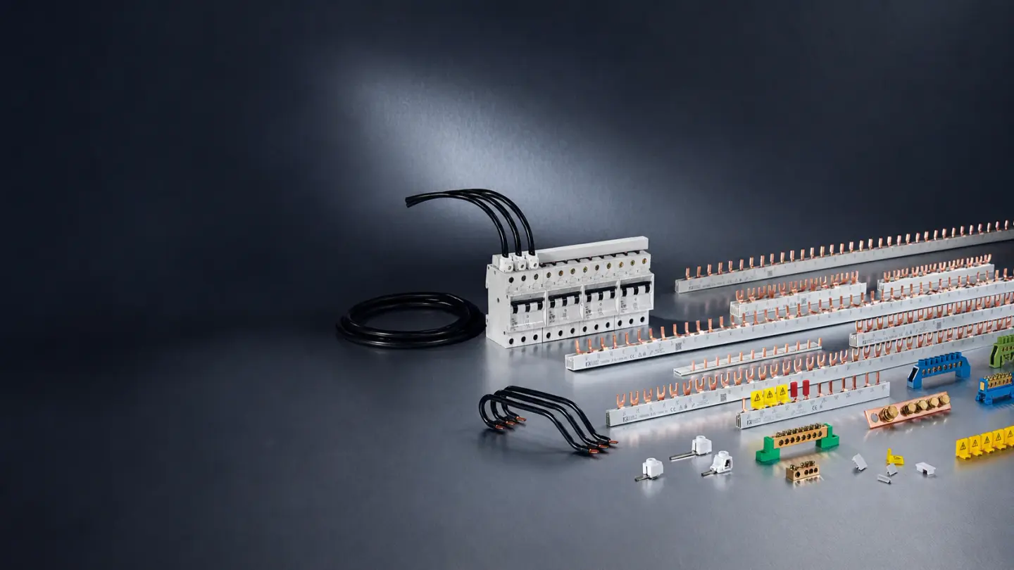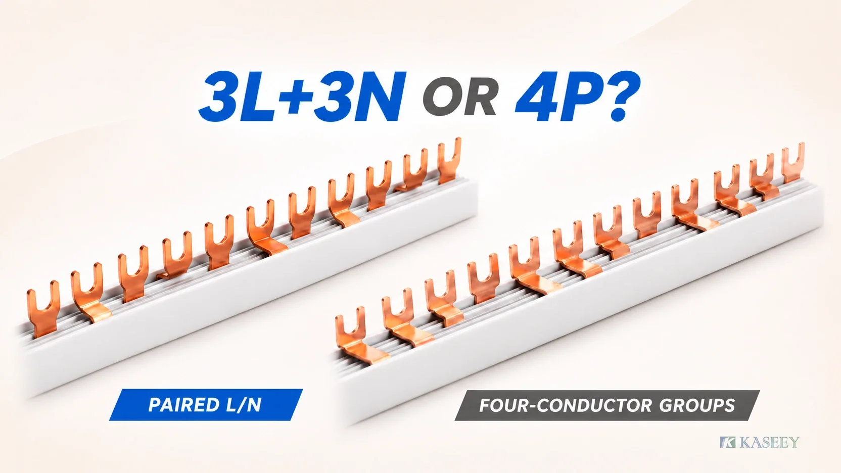
The dividing line is the tooth sequence and the circuit’s neutral obligation. Choose a 3L+3N comb busbar for compatible devices needing repeated phase/neutral pairs; choose a 4P comb for devices taking a complete phase-and-neutral group. Keep neutral outside a phase-only comb when the circuit arrangement calls for separate neutral distribution.
| Configuration | Intended device-row arrangement |
|---|---|
| 3L+3N: (L1,N), (L2,N), (L3,N), repeating | Compatible 1P+N devices, typically individually protected RCBO circuits supplied across the phases |
| 4P: L1, L2, L3, N, repeating | Compatible four-pole or 3P+N devices taking all conductors as a group |
| 3P comb plus separate neutral bar | Three-pole device rows, or phase-only devices whose neutrals share the appropriate upstream RCD group |
For panel builders, OEMs and distributors, this is a configuration decision before detailed specification. A pole label alone does not establish the device’s physical width or terminal layout.
Three configurations, defined by tooth sequence
3L+3N: a phase and neutral for each paired device
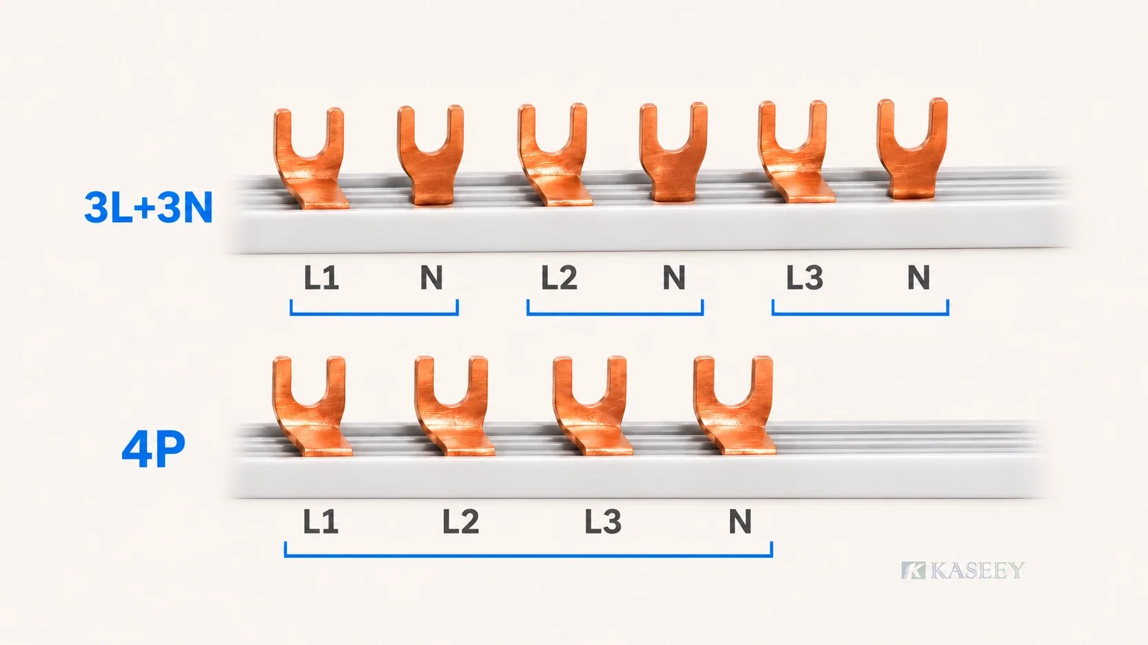
Read the pattern as (L1,N) · (L2,N) · (L3,N), then repeat. Each intended device position receives a phase contact alongside its neutral contact. Successive compatible single-phase devices can therefore be distributed across the incoming phases while retaining paired supply connections.
This arrangement is relevant to rows of 1P+N RCBOs that accept the corresponding comb interface. Each circuit’s load neutral must return through its own RCBO as required by that device’s circuit arrangement. Connecting those load neutrals to a common bar around the individual RCBOs does not preserve that relationship.
Keep the two sides distinct: the comb distributes supply-side phase and neutral connections. It does not combine the outgoing load neutrals or replace their individual return paths. Repeated N contacts on a supply comb are not permission to share load neutrals between separately monitored circuits.
Kaseey’s Fork Type 3L+3N Busbars M6 page publishes the paired sequence and these model-specific values:
| Published item | Fork 3L+3N M6 data |
|---|---|
| Device distance, B | 17.8 mm |
| Fork width / fork length | 11 mm / 13.5 mm |
| Available cross-sections | 8 / 10 / 13 / 16 mm² |
| Corresponding reference currents | 50 / 63 / 70 / 80 A |
| Published lengths | 210 / 1000 mm |
| Published module counts | 12 / 54 |
These are reference currents for the published models, not an unconditional assembly rating. The selected model and application documents still govern acceptance.
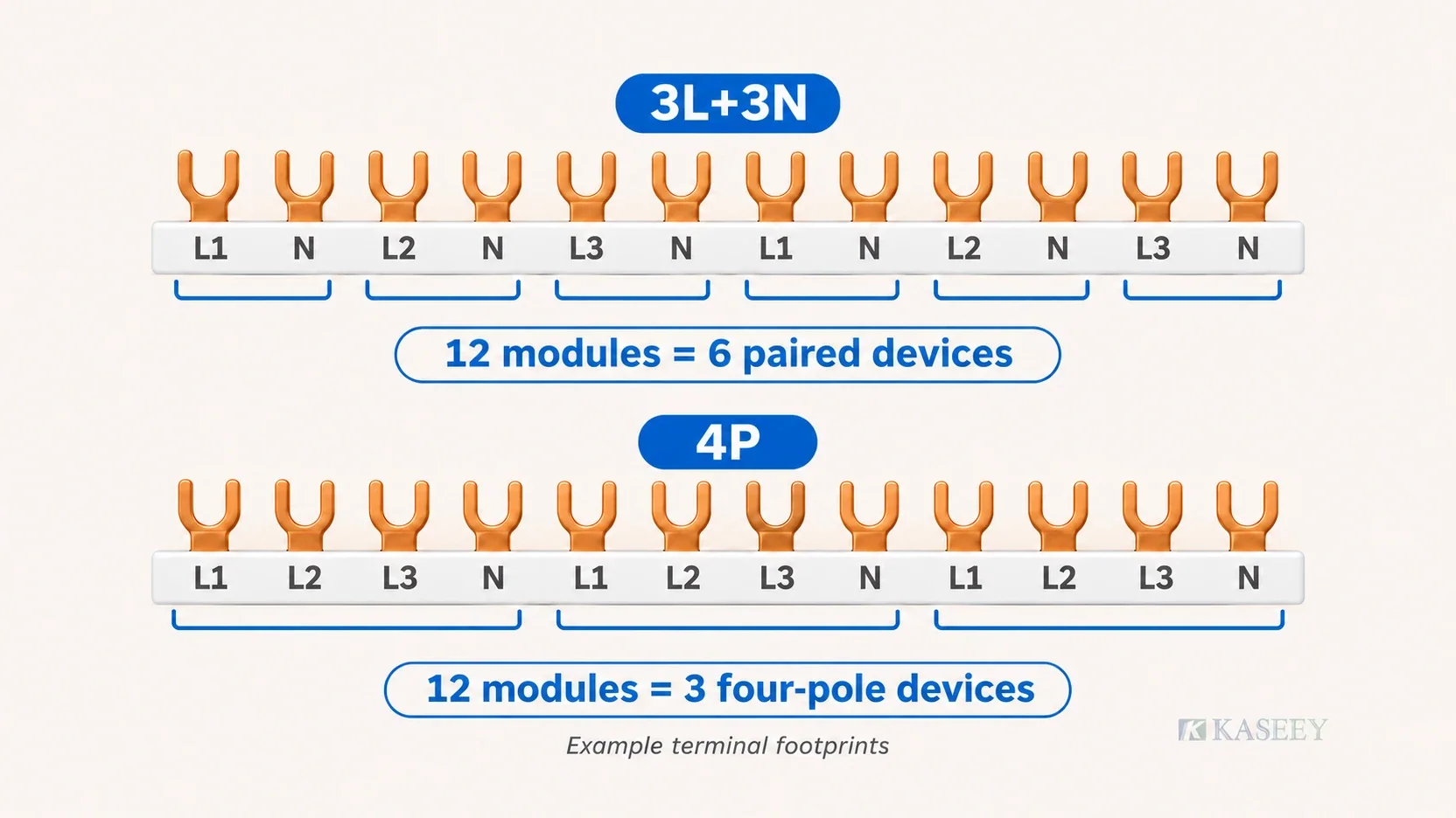
In the paired terminal-footprint example used here, 12 modules form 6 L/N pairs for 6 compatible 1P+N devices; 54 modules form 27 pairs for 27 devices. This arithmetic assumes each device uses the illustrated pair of positions. It must not be transferred automatically to a compact device or a different contact layout.
Kaseey also lists a pin-type 3L+3N family and a pin-S family. They are related configuration choices with different connection forms; the fork dimensions above are not their specifications.
4P: a complete conductor group for each device
The pattern is L1 · L2 · L3 · N, repeating. A compatible four-pole or 3P+N device receives the complete group, rather than a separate phase/neutral pair for each single-phase circuit. The same cycle can serve a specified four-wire supply distribution arrangement when the connected terminals and circuit drawing require it.
Kaseey lists Fork Type 4-Phase Busbars M6 and a pin-type P-4L family. Their existence provides the product-family counterpart for this comparison; no dimensions or current values from those ranges are assumed here. The catalogue’s family name does not change the L1/L2/L3/N arrangement being discussed.
For the stated four-position device footprint, 12 modules form 3 complete groups for 3 four-pole devices. A 3L+3N comb cannot substitute merely because both arrangements distribute phase and neutral: their successive contact identities differ.
3P comb plus a separate neutral bar
Here the comb repeats L1 · L2 · L3, with no neutral teeth. Where the circuits require neutral, that conductor follows a separate distribution component and the approved circuit arrangement. A three-pole load that does not require neutral does not gain a neutral connection simply because the panel contains a neutral bar.
This can suit motor and control rows of three-pole devices. It can also suit phase-only single-pole devices protected together by an upstream RCD, with their neutrals terminating on the neutral bar belonging to that same protected group. It does not authorize neutral connections between different RCD groups.
The separate component’s construction and mounting belong to Kaseey’s brass neutral and earth distribution guide. Here, the decision is whether neutral belongs in the comb’s repeating contacts or in a separate distribution path.
The decision
Start with the devices actually occupying the row
A compatible row of individual 1P+N RCBOs points toward paired contacts. A row of four-pole devices points toward complete L1/L2/L3/N groups. A three-pole device row points toward phase-only contacts, with separate neutral distribution where needed.
These are starting configurations, conditional on the exact device interface. The neutral terminal’s position matters as much as its existence. If the proposed sequence puts N where the device needs a phase, or leaves a required neutral terminal unserved, the configuration has failed before any current comparison becomes useful.
Establish the neutral’s circuit obligation
Ask whether each outgoing circuit’s neutral must pass through its own protective device or whether the circuits legitimately share an upstream protective group. With individual RCBOs, preserve each load’s phase/neutral path through the corresponding RCBO. A neutral that bypasses it, or returns through another circuit, can produce an unintended residual-current imbalance and tripping, or make protection behave differently from the intended circuit design.
If the comb supplies the device neutrals, its contacts must form the required pairs. This is why the 3L+3N pattern is useful. Individual protection does not, by itself, mandate a particular comb product: the device’s permitted supply arrangement remains decisive.
Where neutral may collect after a shared upstream RCD, a separate neutral bar can simplify distribution. That common point belongs to the appropriate protected group. Incomer neutral switching depends on the system earthing arrangement and local rules; it is a matter for the incoming device, not the outgoing row’s comb configuration.
Treat neutral as a real current-carrying path
Single-phase load imbalance can leave current in neutral, and third-harmonic components can add in that path. Do not select neutral on the assumption that the phases will always cancel or that an N-labelled contact carries no operating current.
The published fork 3L+3N model table provides a common section selection for the phase and neutral contacts, rather than a separately reduced neutral option. Apply that listed section to both checks and verify the expected circuit neutral current against the selected model’s documentation. A common section designation does not establish adequate capacity for every load mix.
The same obligation exists with a separate neutral bar. Moving neutral outside the comb changes its route and connection component; it does not remove neutral current or its sizing requirement.
Compare space and assembly work
A paired comb can replace separate supply-neutral links to compatible devices and avoid the location those supply connections would otherwise occupy. It still leaves each circuit’s load-neutral termination to be completed correctly. Do not count this as eliminating every neutral wire or every neutral component in the panel.
The tradeoff is a fixed contact pattern. A separate neutral component occupies its own space and needs its associated wiring, but can give the designer more freedom when arranging device groups. Compare the actual enclosure layout, access and accepted device lineup; there is no universal space or labour saving to assign to either choice.
Consider what the next modification will change
For an OEM row repeated without changes, an approved fixed pattern can make the configuration easier to reproduce. Freeze the device lineup and neutral arrangement together so the repeated build remains the same electrical design.
For a row expected to gain circuits or change device types, assess how the configuration accommodates those changes. Separate neutral distribution or intentionally separated device groups may reduce rework. Neither choice excuses a fresh review when the replacement device changes terminal layout or protective grouping. Flexibility is useful only while the intended neutral paths remain intact.
Worked rows
These are configuration examples, not installation instructions or customer case reports. The counts use the terminal footprints stated here, not a universal width inferred from the device name.
Individual RCBO circuits in a residential or commercial panel
Take a three-phase supply feeding compatible 1P+N RCBOs with paired comb terminals. The sequence is (L1,N), (L2,N), (L3,N), repeating. A 12-module paired arrangement provides 6 pairs and therefore serves 6 of these devices. A 54-module arrangement provides 27 pairs and serves 27 devices on the same assumption.
The comb supplies each intended pair. Each outgoing circuit retains its own load-neutral return through its RCBO. A common downstream load-neutral bar cannot be used to bypass those individual return paths. Device widths, terminal sides and permitted feed arrangements must still match the selected product.
A row of four-pole devices
Use the L1/L2/L3/N cycle for devices accepting that complete group. With the example’s four-position footprint, 12 modules divided into complete groups serve 3 four-pole devices.
Substituting the paired pattern would not merely alter phase allocation: it would present neutral contacts at different positions within the intended group. The visible acceptance question is whether every required phase and neutral terminal receives its intended conductor. A missing neutral or a contact assigned to the wrong function is a rejection, not a harmless naming difference.
Three-pole motor/control devices with single-phase auxiliaries
Use a phase-only comb for the compatible three-pole device group. Provide separate neutral distribution for auxiliary circuits that need it, according to their protective arrangement. If the auxiliaries belong to a shared upstream RCD group, keep their neutrals within that group; if separately monitored, preserve their individual device returns.
The presence of auxiliary circuits does not turn the motor-device group into a paired RCBO row. Keep unlike terminal arrangements in deliberately defined sections instead of assuming a continuous comb can serve every device on the rail.
Before you order
Confirm the configuration against the intended row before asking for a part:
- Devices and terminals: identify the exact models, supply terminals and neutral-return arrangement. A 1P+N label alone does not establish the physical footprint.
- Contact form and spacing: confirm the accepted pin or fork interface and the actual terminal spacing. The published fork 3L+3N dimensions describe that family, not the pin, pin-S or 4P products.
- Neutral section: check the selected section against the expected phase and neutral currents and obtain the model-specific application evidence.
- Product identity: retain the selected family, published model, required module count and length together. A request for only a neutral-capable comb leaves the defining configuration unresolved.
Once the configuration is selected, use the existing device-row mapping method to verify the actual contact positions against the intended devices and drawing. That separate review owns the detailed position record; the family decision here does not replace it.
The product records linked above provide the initial family choices. Continue with the complete MCB busbar selection guide for the remaining specification and approval work.
FAQ
Is a 3L+3N busbar the same as a 4P busbar?
No. The paired pattern repeats (L1,N), (L2,N), (L3,N) for compatible phase/neutral device positions. The 4P pattern repeats L1/L2/L3/N for devices receiving the complete group. Both include neutral, but its contact positions differ. Neither configuration substitutes for the other without a different, explicitly verified device arrangement.
Can I use a 3L+3N busbar for plain 1P MCBs?
It is not the intended routine choice. A phase-only device row does not provide the corresponding paired neutral terminals. Trying to use only alternate contacts wastes positions and can place neutral against an unintended terminal. Select the appropriate 1P or 3P phase-only arrangement for the actual row rather than adapting the paired pattern by assumption.
When is a separate neutral bar the better choice?
It can suit a three-pole device row, circuits whose neutrals legitimately collect within a shared upstream RCD group, or a layout expected to change frequently. It provides distribution flexibility at the cost of separate space and wiring. It must preserve protective-group boundaries and cannot bypass the individual load-neutral path of an RCBO.
Does the neutral in a 3L+3N bar carry real current?
Yes. Imbalance and harmonic components can make neutral a loaded conductor. Use the published section for the neutral check as well as the phase check; the reviewed fork model table does not offer a separately reduced neutral selection. Confirm expected neutral current and the complete application conditions rather than assuming balanced phases eliminate the requirement.
What about a mixed row of 1P+N and 3P devices?
Separate the unlike device groups into suitable sections, or establish a specifically verified arrangement using the row mapping method. A single family label does not prove that a continuous comb can serve both patterns. Exact device terminals and protective neutral boundaries determine whether a proposed combination is acceptable.
Sources
All sources are Kaseey records, verified for this comparison. Each record is linked at its relevant point above; direct URLs and claim extracts are also supplied in the delivery source dossier.
- Fork Type 3L+3N Busbars M6 — Kaseey product page and drawing; paired sequence, listed fork geometry, cross-sections, reference currents, lengths and module counts.
- Pin Type 3L+3N Busbars; Pin Type 3L+3N Busbars S-3L+3N — Kaseey product records; qualitative existence of the pin and pin-S connection families. No pin parameters are used.
- Fork Type 4-Phase Busbars M6; Pin Type 4-Phase Busbars P-4L — Kaseey product records; family existence, with the fork drawing supporting the L1/L2/L3/N sequence. No dimensional or current parameters are used.
- Comb Busbar Phase and Neutral Mapping: How to Specify 1P, 1P+N, 3P and 3P+N Rows — Kaseey; distinction between conductor function and physical device layout, and the separate detailed verification task.
- Brass Bars for Neutral and Earth Distribution — Kaseey; separate neutral-component function and the need for a defined circuit arrangement.