Short Answer
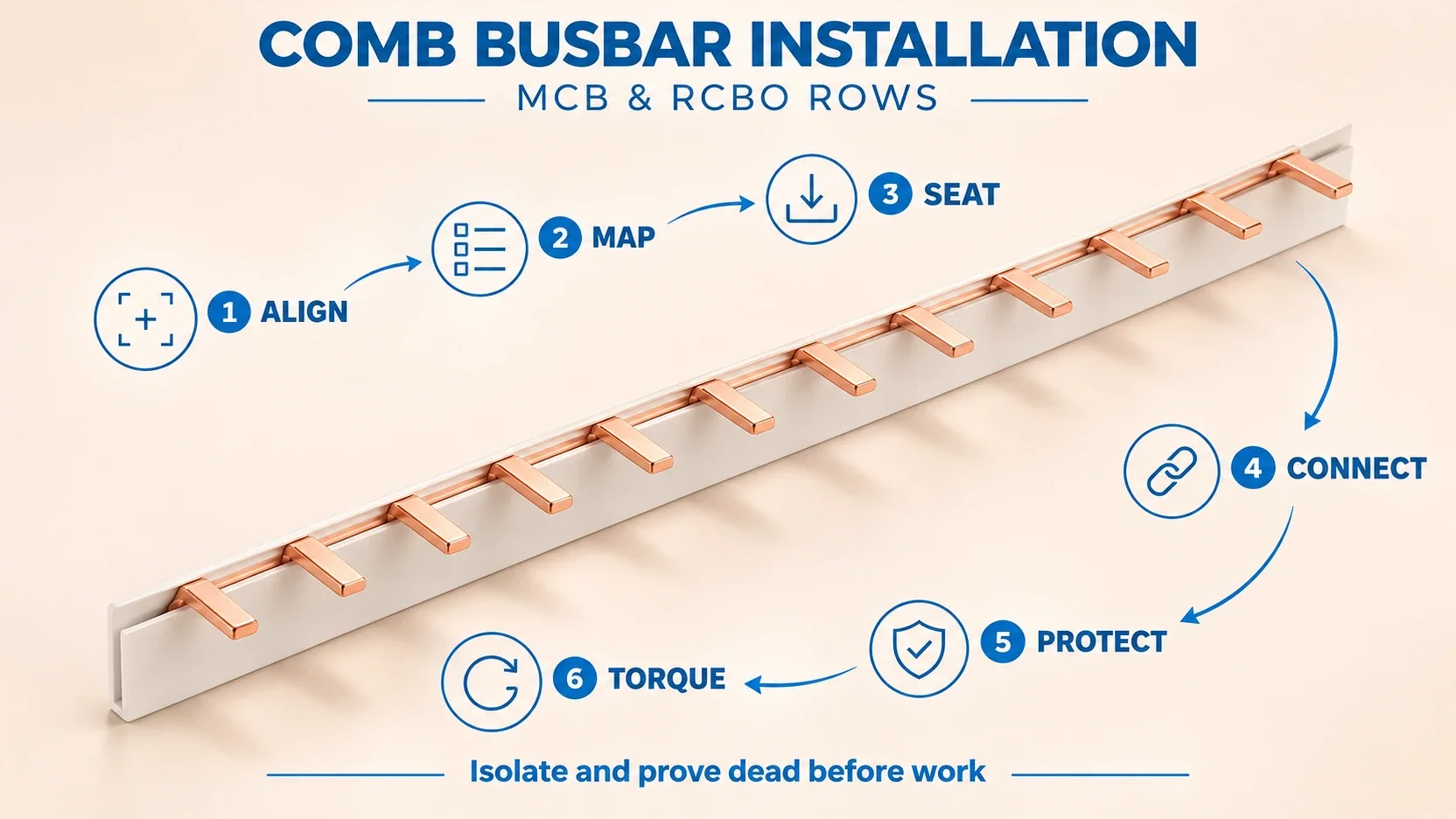
For comb busbar installation, first verify the exact busbar, breakers and distribution board are approved for use together. A qualified electrician must isolate every supply, secure the isolation and prove dead. Then: align the MCBs or RCBOs on the DIN rail; verify busbar orientation and phase-neutral mapping; seat every pin or fork in its specified terminal interface; connect the approved incoming supply arrangement; protect exposed ends and unused teeth; tighten each connection to its own manufacturer’s specified torque; and complete inspection and required testing before energizing.
This guide explains how to install an MCB busbar and what changes when the row contains RCBOs. It assumes the combination has already been selected and approved. Use it alongside the exact device and assembly instructions, which take precedence over this general sequence. The illustrations based on Kaseey product photographs identify features to inspect; they do not demonstrate an approved installed breaker assembly.
Before installation: verify the parts and documents
Use this as a go/no-go checklist, not a selection calculation:
- Contact form: the exact terminal accepts the busbar’s pin or fork interface.
- Pitch: every tooth lines up with its intended terminal across the complete row, including accessories and spaces.
- Pole arrangement: the busbar’s conductor pattern matches the intended device arrangement and phase-neutral schedule.
- Cross-section and contact dimensions: the busbar and tooth dimensions are accepted by the device and assembly documents.
- Electrical suitability: the exact busbar rating and assembly conditions have been checked against the circuit design and upstream protection.
- Documents and accessories: current breaker instructions, busbar identification, approved feed arrangement, end caps and unused-tooth protection are available.
- Condition: no bent contacts, damaged insulation, contamination or unidentified replacement parts.
If any check is unresolved, stop before fitting. Use How to Select an MCB Busbar for the selection worksheet, MCB Busbar Pitch Guide for spacing questions, and MCB Busbar and RCBO Compatibility for model-interface checks.
Have the specified screwdriver bit, a suitable calibrated torque tool, appropriate voltage-testing equipment and the required protective accessories ready. Neither a product photograph nor a matching nominal module width proves compatibility.
Safety and isolation: work only on a proved-dead assembly
Only a qualified electrician competent for the equipment and local installation rules should perform this work. Turning the outgoing breakers off does not establish that the incoming terminals or comb are dead.
Identify all possible supplies, including alternative generation, backup power and control feeds. Isolate and secure them against reconnection under the site’s isolation procedure. Prove dead at the work location using appropriate equipment, and prove the tester immediately before and after use. Protect against adjacent live equipment and address stored energy before touching conductors. If safe isolation cannot be established, do not begin installation.
These principles follow the UK’s HSE guidance, Electricity at work: Safe working practices, particularly its sections on secure isolation and proving dead. Apply the rules for the installation’s own jurisdiction as well.
Step-by-step comb busbar installation
Step 1: Fit and align the breakers on the DIN rail
With isolation established, mount each MCB or RCBO in its planned position using the device’s mounting instructions. Engage the rail clips fully and fit the specified row restraints or end stops. Check that devices sit squarely and that their busbar terminal entries form the intended line.
Offer the comb up to the row without forcing the teeth into place. Check alignment at the first, middle and last positions, then at every intervening terminal. A tooth that drifts off-center farther along the row is a reason to stop and recheck the combination.
Acceptance: the devices are secure, and each intended contact aligns naturally with its receiving interface. Do not use the comb or terminal screws to pull misaligned breakers into position.
Step 2: Confirm orientation and phase-neutral mapping
Read the busbar identification, breaker terminal markings and approved assembly diagram together. Confirm which side of each device is permitted to receive the supply. Do not assume that either end of every MCB or RCBO can be used as the incoming side.
Trace the conductor assignment from the feed point to each receiving terminal. For an RCBO row, identify the exact line and neutral connections, including any separate neutral leads or terminals required by that model. A repeated tooth pattern must not be treated as a phase-neutral map by appearance alone.
Acceptance: every intended tooth has an identified destination, and the resulting line/neutral arrangement matches the approved drawing. Turning a comb around to make it fit is not an acceptable substitute for checking the mapping.
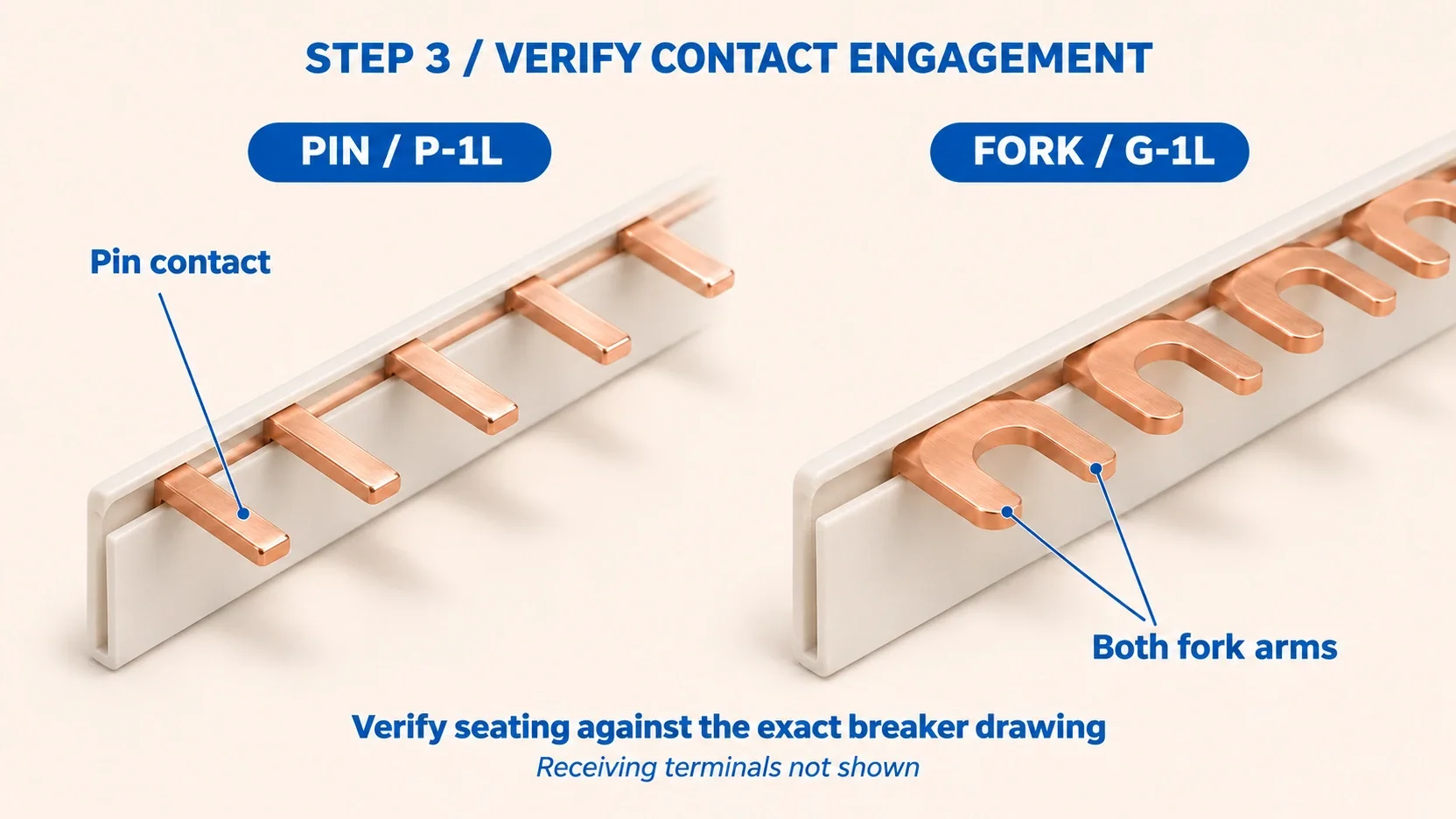
Step 3: Seat every pin or fork in its intended clamping interface
Open the receiving terminals as directed by the breaker manufacturer. Confirm that the intended busbar entry is actually open; a loosened screw alone does not establish the position of the clamping mechanism. Support the comb and engage the row evenly, without bending individual teeth.
| Contact type | What to verify before final tightening | Stop if you see this |
|---|---|---|
| Pin | Each pin enters the specified busbar opening and reaches the documented seated position. The conducting pin, rather than its insulation, occupies the intended contact zone. | A pin alongside or outside the clamp, inconsistent seating, trapped insulation, or a comb that springs back out of alignment. |
| Fork | Each fork enters the designated fork interface and seats as shown in the device drawing. Both arms are correctly positioned under the intended clamping surface. | A fork perched on the wrong side of the clamp, only one arm captured, or a fork riding on insulation. |
For pin contacts, confirm the insertion depth or reference position specified for that exact combination. For fork contacts, verify the actual clamping arrangement; do not assume every fork belongs under any visible screw head.
Acceptance: all contacts meet the device drawing’s engagement criteria, and the carrier is supported without forced distortion. A screw becoming tight does not prove that the contact is captured. If engagement is hidden and cannot be verified by the documented method, stop and obtain the correct instructions instead of guessing. There is no universal insertion depth or visible-copper allowance.
If the length is wrong: remove the comb while the assembly remains isolated. Follow How to Cut a Comb Busbar only if that model is approved for cutting, or obtain the correct factory length. Recheck the finished part before returning to installation. Do not cut a busbar while it is installed in the row.
Step 4: Connect the approved incoming supply arrangement
Use the feed terminal or connector identified in the approved assembly design. Check its permitted conductor material, size, preparation and connection method against its own instructions. Route and support the incoming conductor so it does not pull the comb out of its seated position.
If the incoming conductor and comb connect at the same breaker, confirm the exact permitted arrangement. A terminal that accepts a cable and one that accepts a comb do not automatically permit both in the same clamping space. Use only the documented shared or separate connection paths.
Acceptance: the feed is in its intended connection point, the conductor is fully captured as specified, and the comb remains seated. Revisit Comb Busbar Feed-In Point Planning if the feed location has changed; do not redesign it by improvising during installation.
Step 5: Fit end protection and cover unused teeth
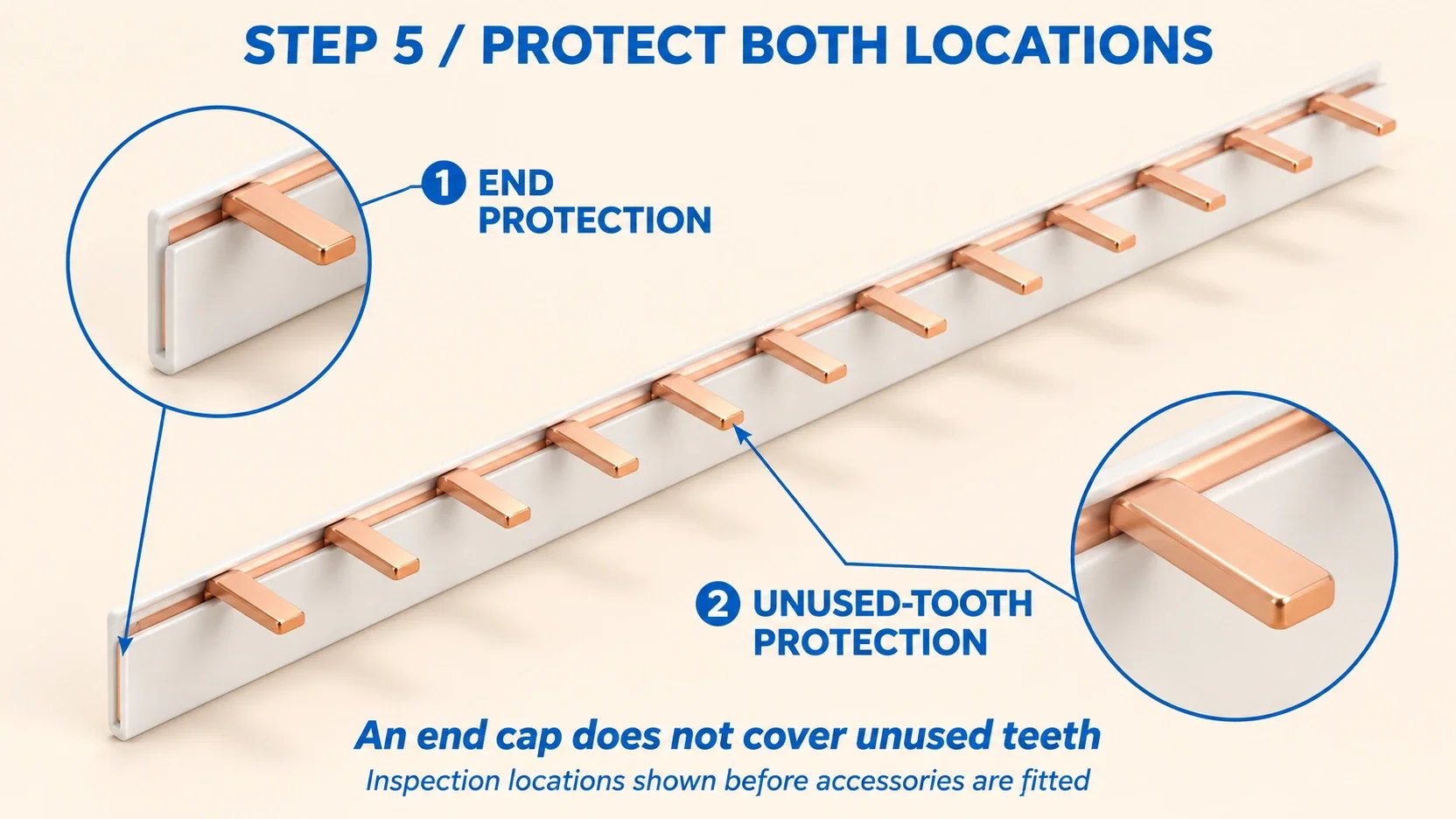
Fit the busbar manufacturer’s specified end protection to every end that requires it, including a permitted cut end. Fit compatible tooth covers wherever unused teeth would otherwise remain exposed. Confirm each accessory is seated and retained according to its instructions.
An end cap protects the end of the busbar profile; it does not cover the projecting teeth along the row. Likewise, a front blanking plate does not establish that an unused tooth behind it is adequately protected.
Acceptance: all required end and unused-contact protection is in place, secure and undamaged, without displacing the comb. Follow any assembly-specific accessory fitting order. For spare-position arrangements, use MCB Busbar Spare Ways.
Step 6: Tighten each terminal to its documented torque
Use the torque stated in the breaker manufacturer’s document for the exact model, terminal and busbar connection. Use the separate connector manufacturer’s value for a dedicated feed connector where applicable. Confirm the units and use the specified tool and bit.
Keep the comb seated while tightening. Follow the manufacturer’s sequence if one is specified; otherwise use a controlled position-by-position check so no terminal is missed. Record the document reference, applicable torque, terminal positions and completion of tightening. Recheck contact engagement after tightening and after any cable movement that could disturb it.
Acceptance: every required connection is correctly engaged and tightened to its own documented value. Do not use a generic internet torque, an adjacent device’s value or an arbitrary extra turn. If the applicable value cannot be verified, leave the assembly isolated until the exact model instructions are obtained.
Pre-energization inspection checklist
Complete this inspection while the assembly remains isolated. Visual inspection and a torque record do not replace the electrical verification required for the installation.
| Check | Release condition |
|---|---|
| Device mounting | All rail clips and required restraints are secure; the row is aligned. |
| Contact engagement | Every pin or fork meets its documented seating condition; no trapped insulation or distorted contact is present. |
| Orientation and mapping | Supply side, phase sequence where applicable, line/neutral assignments and RCBO neutral connections match the approved drawing. |
| Incoming supply | The correct feed point and permitted conductor arrangement are used; cable routing does not stress the comb. |
| Tightening | Every breaker and feed connection has a documented applicable torque and completed tightening record. |
| Protection | Required end caps, unused-tooth covers, barriers and enclosure covers are fitted correctly. |
| Cleanliness | No loose strands, metal swarf, tools or other debris remain; insulation is undamaged. |
| Verification | The qualified electrician has completed and recorded the required dead tests and pre-energization checks under local rules and device instructions. |
Choose electrical test methods appropriate to connected equipment; follow device instructions before applying insulation tests that could affect electronics. Do not infer test voltages or pass limits from this generic guide.
After the pre-energization checks pass, restore covers and release the isolation only under the authorized commissioning procedure. Complete any required energized verification and RCBO functional testing in that controlled stage. An RCBO’s test button is not a substitute for the installation’s required verification. If a defect is found, isolate and prove dead again before correction.
Common installation mistakes
| Mistake | What it can look like | Correct response |
|---|---|---|
| Teeth not fully inserted | The screw feels tight, but one contact sits higher or outside its intended clamp. | Keep isolated; reopen the affected connection and verify seating against the exact terminal drawing before tightening again. |
| Forcing a pitch mismatch | Early contacts align but later teeth drift, bend or pull devices sideways. | Remove the comb and resolve the mismatch. Do not bend teeth or force the row together. |
| Installing the comb in reverse | The strip physically fits, but the permitted supply side or line/neutral assignment no longer matches the plan. | Reconfirm the orientation and complete mapping before reconnecting. |
| Leaving unused teeth exposed | An end cap is fitted, but spare projecting contacts remain uncovered. | Fit the specified unused-tooth protection and verify the complete protective arrangement before release. |
FAQ
Can the same comb busbar be installed on both MCB and RCBO rows?
Only when the exact busbar, devices and board are approved for that combination. Confirm contact form, pitch, terminal geometry, conductor pattern and the permitted supply side. RCBO neutral connections must follow the specific RCBO diagram. Matching module widths or a successful physical trial fit do not establish electrical compatibility.
How do I know a pin or fork busbar is fully seated?
For a pin busbar, verify that each pin occupies the intended clamping zone and reaches the seated position specified by the device manufacturer. For a fork busbar, verify that both arms are correctly captured by the designated clamping interface. Check every position before and after tightening. A tight screw, a straight-looking carrier or a neighboring contact’s position is not sufficient proof.
What torque should I use for comb busbar terminals?
Use the breaker manufacturer’s specified torque for the exact model and busbar terminal connection. A separate feed connector may require a different value from its own instructions. Use an appropriate calibrated torque tool and record the applicable values. If the model-specific torque is unavailable, do not substitute a universal number or energize the unfinished assembly.
Can I cut a comb busbar to fit the row?
Only cut a busbar if its manufacturer permits cutting that model. Remove it from the isolated assembly, follow the product’s cutting instructions and restore the required end protection before installation. If cutting is not permitted or the instructions are unavailable, obtain a correctly sized approved part. Never trim an installed comb inside the breaker row.
Do unused busbar teeth need covers if an end cap is fitted?
Unused teeth require the protection specified for the assembly even when the profile has end caps. An end cap and an unused-tooth cover protect different locations. Fit the compatible protective accessories and verify their retention before energizing; neither tape nor a front blanking plate should be assumed to replace the specified tooth protection.
Confirm the exact combination before building the row
For a Kaseey busbar installation review, provide the busbar model, full breaker or RCBO references, row drawing, intended feed arrangement and destination market. Request the applicable product drawing and accessory details before assembly. The practical release condition is a correctly seated, mapped, protected, tightened and verified row supported by the exact product documents.
Sources
- Pin Type 1-Phase Busbars (P-1L) – Kaseey. Source product and exterior photograph for the straight-pin contact and protection-location annotations; not evidence of compatibility with an unspecified breaker.
- Fork type, 1 phase busbars G-1L – Kaseey. Source product and exterior photograph for the fork-contact annotation; not an installed-terminal drawing.
- Electricity at work: Safe working practices, HSG85 – UK Health and Safety Executive, third edition, 2013. Competence, secure isolation and proving-dead guidance; apply alongside the installation’s local requirements.