Respuesta corta
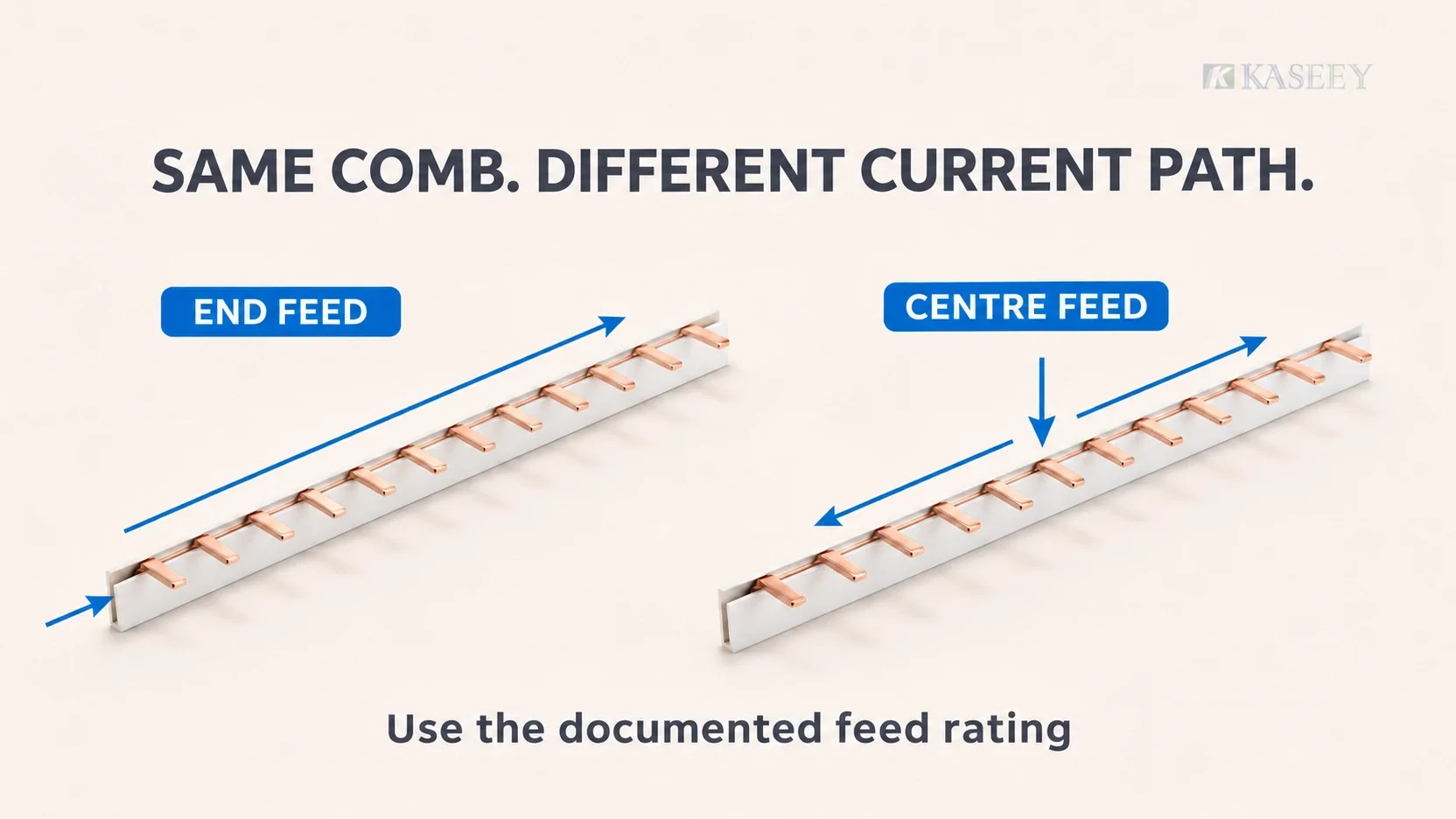
The same comb busbar can have a centre-feed rating twice its end-feed rating because the incoming current splits into left and right branches: with equal loading, each branch carries half the total, and neither may exceed its documented limit. This is not a universal multiplier or a free capacity upgrade. Some documented products have a smaller increase, and the permitted total depends on load distribution, feed connections and the manufacturer’s stated conditions.
For panel builders comparing end feed vs centre feed, the question is not simply how much copper the comb contains. It is which section carries the combined load, how that section heats up, and whether the incoming connection can carry the proposed total.
The product-specific examples below include a doubled rating and a smaller increase. They are separate manufacturer records, not a common ampacity table or evidence that one manufacturer’s rating applies to another comb.
Why changing the feed position changes the current path
End feed: the section nearest the supply carries the combined load
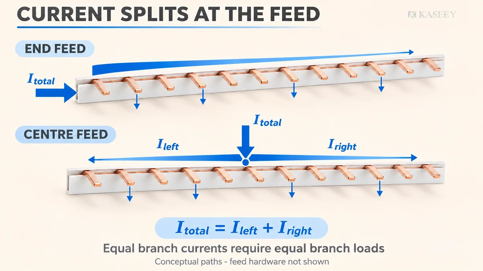
With a supply connected at the end, current enters the comb and is taken off through successive outgoing devices. The section immediately downstream of the feed carries the sum of the loads beyond it. As each circuit takes current, the current remaining in the next section falls.
It is therefore inaccurate to say that every part of an end-fed comb always carries the total row current. The important point is that the common section near the incoming connection must carry that total before it divides among the outgoing circuits.
Centre feed: the incoming current divides between two branches
With a permitted feed near the centre, the incoming current supplies loads to the left and right. For one conductor in the illustrated arrangement:
- I_total = I_left + I_right.
- I_left is the combined load supplied on the left branch.
- I_right is the combined load supplied on the right branch.
Equal branch demand gives an equal split. Merely connecting at the physical midpoint does not make unequal loads draw equal current. Each branch section carries the downstream demand on its own side, decreasing as loads take current from the comb.
Where a manufacturer permits twice the end-feed total, the reasoning is that neither branch needs to carry more than the documented branch limit under the specified arrangement. The feed connection itself still carries the combined incoming current.
Temperature rise is the limiting physical issue
For a conductor section, resistive heating follows I squared times R. Routing the entire row current through a common section creates more local heating than dividing that current between separate branches of the same conductor section. This explains why moving the feed can change the usable total without increasing the copper cross-section.
The design still has to meet the applicable temperature-rise limits. Insulation, contact resistance, neighbouring devices, ambient conditions and enclosure heat dissipation remain relevant. The limiting point can also be a tooth, clamp or feed terminal rather than the long copper conductor.
The physics explains the direction of the effect; it does not determine a product rating by itself. Compare feed arrangements under the manufacturer’s specified thermal conditions and construction. Do not assign a doubled rating merely because the copper section is unchanged.
For bare-conductor ampacity methods, see Copper Busbar Current Capacity; its cross-section tables do not establish a finished comb assembly’s feed-dependent rating.
Verified manufacturer ratings: read each row with its own conditions
The following values were checked in the manufacturers’ publicly available documents. Each row identifies its own product scope and source. Neither the current figures nor the connection assumptions transfer between rows.
| Manufacturer and documented product | End or side feed | Centre or middle feed | Scope and qualification | Original product document |
|---|---|---|---|---|
| Woehner, comb-type busbar 31548, single-pole bridge type | 100 A, end feed | 200 A, centre feed | The manual identifies this specific comb for its fuse-holder system. It is not a universal MCB-comb rating. Its current product record says the centre-feed capacity was tested under specific conditions, which must be requested before panel design. Confirm the intended feed hardware. | Manual 2020, Panel chapter, printed page 6/8 |
| ABB, busbars PS…BP-C/CR | 100 A, end fed | 200 A, center fed | Rated current per phase in the named family. The footnote expressly requires that the MCB terminal’s current capacity/rating must not be exceeded. | Miniature Circuit Breakers US Catalog, technical specifications, printed page 18 |
| ETI, fork phase busbars IZ16/2F/56, IZ16/3F/57 and IZ16/4F/56 for the stated ETIMAT P10 devices | 80 A, side connection | 130 A, middle connection | The technical table is stated at 35 degrees C ambient. The note limits the sum of outgoing currents on each rail branch to the stated Is/phase limit. Follow the same table’s connection requirements. | ETIBOX catalogue, printed page 868 |
Woehner’s 31548 product record explicitly qualifies its centre-feed capacity by test conditions and asks designers to obtain them before designing a panel.
The ETI row shows why “centre feed always doubles the rating” is unsafe. Its published middle-feed figure is below twice its side-feed figure. Use the actual middle-feed rating, the branch limits and the specified connections together.
Also distinguish a busbar rating from a feed-terminal rating. The Woehner manual lists connection hardware separately, including hardware rated below the busbar’s quoted centre-feed total. That is a reason to obtain the permitted feed arrangement, not permission to overload a single connector or improvise parallel connections.
Kaseey: confirm the paired ratings for the exact order model
Kaseey’s P-1L product page publishes model-specific reference-current information, but the reviewed public page does not identify a paired end-feed and centre-feed rating. It directs buyers to request controlled product documentation.
Accordingly, no numerical Kaseey end/centre pair is assigned here. Ask for the exact order model’s permitted feed arrangement, total and branch limits, compatible feed hardware, thermal conditions and supporting document revision. Do not relabel its published reference current as an end-feed value and multiply it. A verified rating pair for the selected Kaseey model is needed before designing around a higher centre-feed total.
How to choose the feed arrangement from the rating
When a higher-capacity feed arrangement is needed
If the intended design current exceeds the documented end-feed rating, the existing end-feed arrangement is insufficient. A documented centre-feed arrangement may be a solution when all of the following are satisfied:
- The exact comb has a stated centre-feed rating covering the intended total.
- Each branch’s demand remains within its documented limit for all intended operating combinations.
- The incoming cable, feed connector and any device terminal in the path support their actual current.
- The assembly’s thermal conditions, protection and installation match the applicable documentation.
Centre feed is not the only possible redesign: a higher-rated comb or a separately supplied distribution arrangement may be required. If the manufacturer has not approved centre feeding for the selected model, moving the cable is not a valid remedy.
For a long row, feeding closer to the electrical load centre can reduce the heavily loaded path length and can help voltage-drop and temperature-rise management. Length alone does not establish that centre feed is mandatory or sufficient. Check the actual load distribution and thermal limits; the far end of a lightly loaded branch does not behave like the feed section.
When end feed is enough
End feed can be appropriate where the design demand stays within the documented end-feed rating and all connection, thermal and protection conditions are met. A higher centre-feed label does not make an otherwise compliant end-fed row inadequate.
For the separate task of arranging positions and branch groups, use Planificación del punto de entrada de alimentación de peine y barra colectora.
Coordinate the incoming terminal and cable with the full current
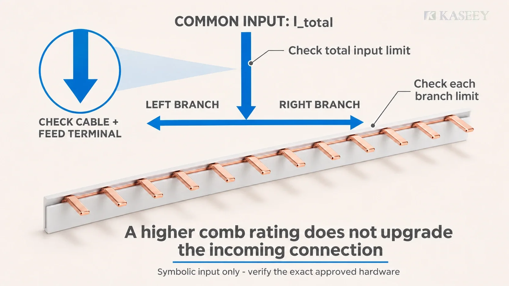
A centre-fed comb divides current after the common incoming path. That common path still includes the supply cable and the actual input connection. Verify the connector’s current rating, accepted conductor type and cross-section, preparation and tightening requirements against its own instructions.
Do not choose a cable solely because it fits the connector. Its required ampacity depends on the installation method, ambient conditions, grouping and applicable protection requirements. Conversely, a cable with adequate ampacity does not upgrade a lower-rated terminal. Use the manufacturer’s prescribed feed arrangement; do not assume two conductors or two feed points can simply be added together.
Apply the check separately to 1P, 3P and 4P combs
| Disposición | Rating check that matters |
|---|---|
| 1P | Compare the incoming total and the two branch demands for that conductor. Confirm the exact feed interface and permitted device combination. |
| 3P | Work per phase. Check each phase’s left and right demand and its incoming connection; a balanced total across the board does not prove that each branch of each phase is within its limit. Preserve the documented phase sequence. |
| 4P, including 3P+N arrangements | Confirm the actual pole pattern and neutral function. Check neutral loading and the neutral feed path under the intended loads; do not assume a neutral is unloaded or that all four conductors have identical application limits. |
A pole count or matching module width does not prove electrical or mechanical compatibility. Use Cómo seleccionar una barra colectora MCB y la la Guía de paso de barras colectoras de MCB for those separate checks.
Common rating mistakes
Treating a centre-feed total as valid at any connection point. The higher figure belongs to a defined feed arrangement and load distribution. Moving the input toward an end can leave a heavily loaded branch carrying more than permitted.
Reading only the ampere figure. Confirm whether the figure describes end feed, middle feed, a branch, a phase or a connector. Retain the table heading, footnotes and product reference with the number.
Applying bare copper ampacity to a finished comb. A comb includes contact geometry, insulation and interfaces with other devices. A bare-strip table does not cover that assembly.
Assuming the input terminal also gains capacity. Splitting current along the comb does not reduce the current in a single common incoming terminal. The limiting connection still governs.
After the rating and arrangement are confirmed, follow How to Install a Comb Busbar for the separate installation sequence. Any alteration requires competent personnel, safe isolation and the exact product and assembly instructions.
Preguntas frecuentes
Can centre feed allow more than twice the end-feed rating?
Do not exceed a manufacturer’s published centre-feed rating or derive one by multiplication. A centre-fed arrangement divides demand between branches, but the permitted total also depends on the connection, thermal conditions and product construction. Even twice the end-feed value is not universal, as the documented ETI example demonstrates. Any proposed higher value needs explicit evidence for that exact product and arrangement.
What if the loads on the two sides are unequal?
Calculate the demand on each side separately for each relevant conductor or phase. A feed at the midpoint does not force an equal split. The heavier branch must remain within its documented limit, and the combined current must remain within the centre-feed and incoming-connection limits. If a branch exceeds its allowance, revise the load grouping or select another documented arrangement; spare capacity on the other side does not cancel an overload.
Can I convert an existing end-fed comb to centre feed?
Only after confirming that the exact comb, devices, enclosure and feed hardware permit the new arrangement. Recheck branch demands, the incoming path, phase/neutral mapping, protection and required thermal verification. The work must follow safe isolation and the relevant installation instructions. Moving the cable to a middle terminal alone does not establish a higher rating.
Does a centre-feed rating apply per phase or to the whole board?
Use the wording in the product document. ABB’s cited PS…BP-C/CR table states rated current per phase, and ETI’s branch note is also phase-specific. Do not add phase ratings into a single conductor rating or assume the neutral has no load. Each conductor, branch and incoming connection must meet its applicable limit.
Can I double a Kaseey comb’s published reference current?
No. The reviewed Kaseey P-1L public page provides reference-current information without a separately identified end-feed/centre-feed pair. Obtain the exact order model’s controlled rating document, approved feed hardware and branch/thermal conditions before using a centre-feed figure. Another manufacturer’s rating pair and a schematic current split do not establish a Kaseey rating.
Keep the rating tied to the feed arrangement
For a Kaseey rating review, provide the comb order model, device references, intended feed connection, load demand on each side and phase, and enclosure conditions. Request the documented total, branch and feed-connection limits together. The usable rating is the one supported for the complete arrangement, not the largest number found beside a similar comb.
Fuentes
-
Comb-type busbar 31548 product record – Woehner. Test-condition qualification for centre-feed capacity and connection notes.
-
Manual 2020, Panel chapter, printed page 6/8 – Woehner. Part 31548 end/centre rating pair and separate connection-hardware data; PDF page 7.
- Miniature Circuit Breakers US Catalog, PS…BP-C/CR technical specifications, printed page 18 – ABB, document 1SXU400208C0201, file revision 1116. End/center rated current per phase and MCB-terminal footnote; PDF page 20.
- ETIBOX catalogue, fork section rails for ETIMAT P10, printed page 868 – ETI. Side/middle rating pair, ambient and connection conditions, and per-branch limit; PDF page 52.
- Tipo espiga 1-Barras colectoras de fase (P-1L) – Kaseey. Published model reference-current information and original product photograph; the reviewed page does not establish a paired end/centre rating.