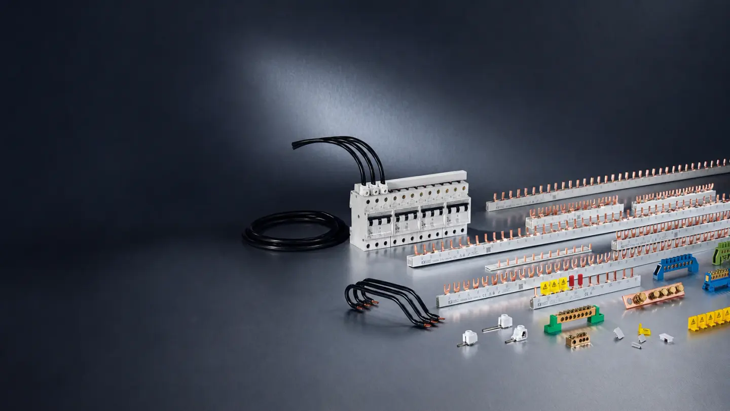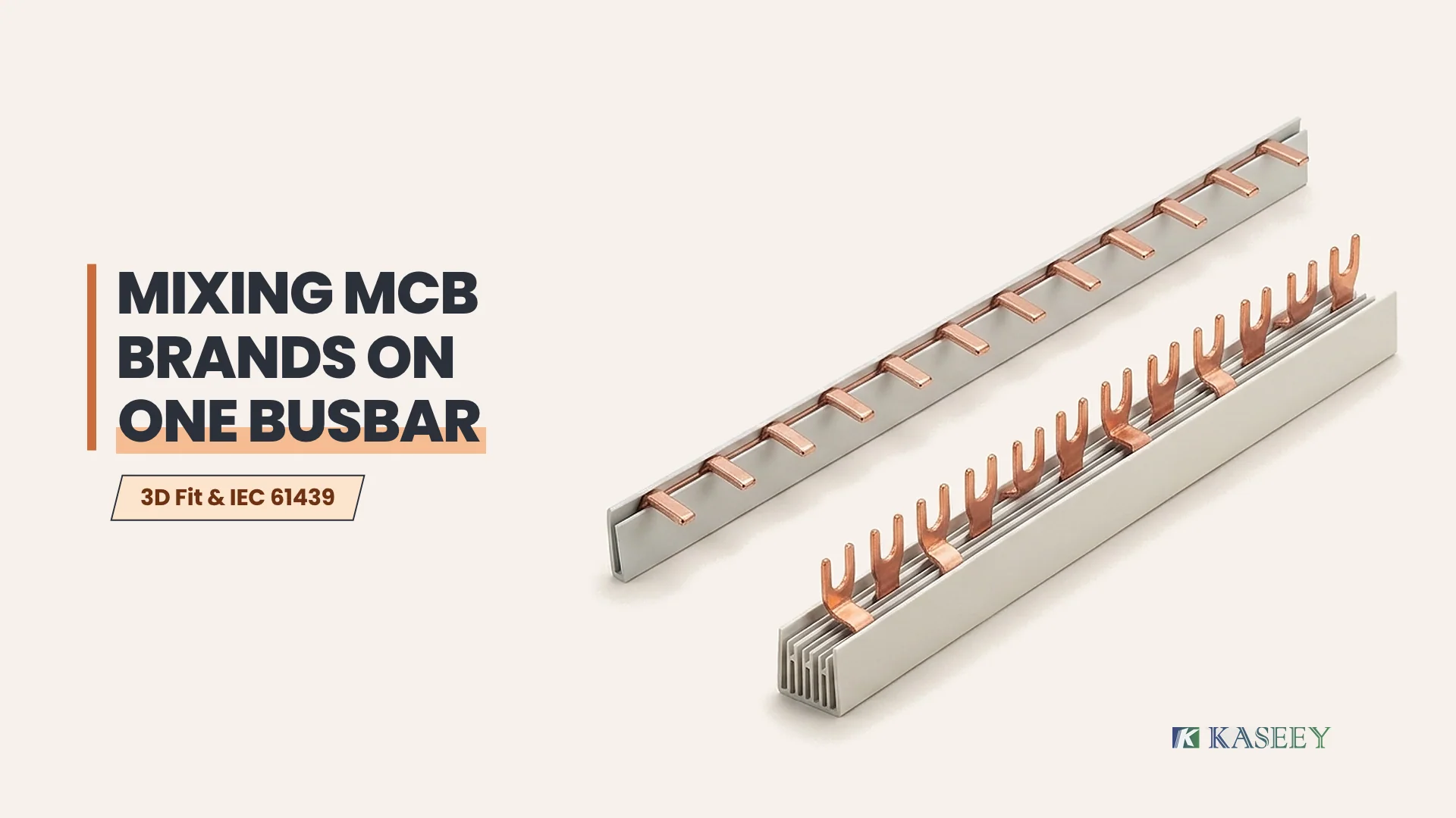
Do not connect miniature circuit breakers (MCBs) from different manufacturers onto a single rigid comb busbar unless written assembly documentation confirms identical three-dimensional terminal geometry and verified short-circuit coordination. Even when two breaker families clip onto the same 35 mm DIN rail and share a nominal 18 mm module width, hidden offsets in terminal cage height, throat depth, and clamping plane prevent uniform copper contact across the row.
This compatibility analysis covers modular DIN-rail distribution assemblies governed by IEC 61439-1:2020 and IEC 61439-3:2024 (outgoing circuits up to 125 A and assembly ratings up to 250 A) alongside North American UL 67 and UL 508A panelboard and industrial control panel listing boundaries under NFPA 70 (NEC) Section 110.3(B). Exact torque, conductor capacity, and terminal jaw geometry always remain governed by the installed breaker and busbar manufacturer datasheets.
Why Shared 35 mm DIN Rails Do Not Guarantee Comb Busbar Alignment
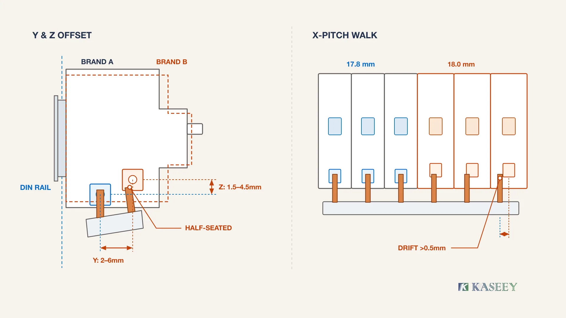
Standardized 35 mm top-hat mounting rails defined under IEC 60715:2017 lock only the rear latching clip of an MCB to the enclosure backplate, while IEC 60898-1:2015+AMD1:2019 governs electrical tripping performance rather than a universal terminal-cage position. Consequently, two DIN-rail breakers from different manufacturers routinely diverge across three orthogonal axes (X, Y, and Z) at the busbar entry plane.
When an electrician slides a rigid copper comb busbar across a mixed-brand row, the copper strip acts as a fixed three-dimensional gauge. A mismatch on any single axis forces the installer either to torque a skewed tooth against the edge of the cage clamp or to flex the insulated copper bar out of plane. While horizontal pole-to-pole spacing is covered in detail in our MCB busbar pitch measurement guide, cross-brand mixing adds two additional failure planes—front-to-back throat depth (Y-axis) and vertical rail-to-clamp height (Z-axis)—that horizontal pitch checks alone never catch.
| Alignment Axis | Geometric Reference Datum | Typical Cross-Brand Variance | Physical Result on One Rigid Comb Busbar | Go / Reject Threshold |
|---|---|---|---|---|
| X-Axis (Horizontal Pitch) | Center-to-center distance across poles | 17.5 mm vs 17.8 mm vs 18.0 mm per pole | Cumulative walk of 2.4 to 6.0 mm over a 12-pole row; side-loading of tooth insulation | Reject if cumulative drift exceeds 0.5 mm across the connected span |
| Y-Axis (Throat Depth Plane) | Distance from DIN rail rear face to terminal cage center | 2.0 to 6.0 mm step between single-chamber and dual-chamber terminals | Cantilever bending of copper busbar; rear-offset brand traps tooth at jaw edge | Reject any step exceeding 1.0 mm without a stepped OEM profile |
| Z-Axis (Vertical Clamp Height) | Distance from 35 mm DIN rail centerline to terminal stop | 1.5 to 4.5 mm difference in tooth insertion depth | Shallow-seating brand clamps only the tooth tip or pinches PVC insulator skirt | Reject if copper tooth insertion falls below 80% of rated jaw depth |
| Clamp Geometry (Pin vs Fork) | Terminal jaw width, screw head collar, and dual-slot divider | Pin thickness 1.0 to 2.0 mm vs M5/M6 fork opening 4.5 to 6.5 mm | Fork slot bottoms out on larger screw shank or pin misses upper cage slot | Reject immediately when terminal style or screw-shank clearance conflicts |
Any mixed-brand MCB row showing more than 0.5 mm cumulative X-axis drift or more than 1.0 mm of Y-axis or Z-axis terminal offset must be physically separated rather than forced onto a single straight comb busbar.
Mechanical and Thermal Failure Modes When Mixing MCB Brands on a Busbar
Forcing a single comb busbar across mismatched MCB terminal planes concentrates clamping force onto a narrow line edge of the copper tooth instead of the full flat contact land. Under continuous load current, reduced contact area increases local joint resistance, drives progressive thermal oxidation, and can loosen the terminal screw through repeated thermal cycling.
Four distinct failure mechanisms emerge in field-inspected panels where mixed-brand breakers share one comb bar:
- Cantilever bending and spring-back torque loss: When Brand B’s terminal cage sits 3 mm forward or higher than Brand A’s cage, tightening the terminal screws bows the rigid copper bar. Over weeks of load cycling, mechanical spring-back in the copper strip unloads the clamping screw on the weaker terminal, creating an intermittent high-resistance joint.
- Insulator skirt pinching: A Z-axis vertical height mismatch frequently pushes the deeper-seated breaker’s cage jaw onto the chamfered shoulder or PVC/PA66 insulating profile of the comb busbar. The screw feels tight on a torque screwdriver, yet the electrical contact rests on only a fraction of the copper pin width.
- Misaligned dual-chamber vs single-chamber clamps: Some modular breakers place a dedicated rear comb-busbar slot behind the main cable cage, while other brands accept both pin and cable inside one shared cage. Mixing both architectures on one comb bar leaves the single-chamber device skewed relative to the dual-chamber slot. (For details on choosing between pin-type and fork-type contact surfaces on matched rows, see our pin-type vs fork-type comb busbar guide.)
- Reduced phase-to-phase creepage and micro-arcing: Twisting a multi-phase (2P, 3P, or 4P) comb busbar to bridge misaligned terminals stresses the extruded insulating housing and can crack inter-phase barriers or lift adjacent teeth closer to neighboring cage screws. Once copper oxidation or insulator discoloration appears, the entire bar must be replaced—see our comb busbar replacement inspection criteria for thermal damage thresholds.
IEC 61439-3 and UL 67 Compliance Boundaries for Mixed-Brand Breaker Rows
Under IEC 61439-1:2020 and IEC 61439-3:2024, a distribution board is verified as a complete assembly—enclosure, comb busbar, terminals, and specified protective devices tested together for temperature rise and conditional short-circuit withstand. Substituting an unverified MCB brand onto an existing comb busbar invalidates the original manufacturer’s design verification and transfers full assembly verification responsibility onto the installer or panel builder.
Compliance boundaries differ sharply between IEC distribution boards and North American listed panelboards, yet both frameworks restrict ad-hoc cross-brand mixing on a shared busbar:
| Governing Framework | Standard & Scope | Effect of Mixing Unverified MCB Brands on One Comb Busbar | Legal / Verification Consequence |
|---|---|---|---|
| IEC Distribution Boards (DBOs) | IEC 61439-3:2024 (outgoing circuits ≤ 125 A, assembly ≤ 250 A) & IEC 61439-1:2020 | Invalidates original manufacturer’s design verification for temperature rise (typically 70 K busbar limit) and conditional short-circuit rating | Installer or panel builder legally assumes the role of Original Manufacturer and must re-verify thermal and fault performance |
| North American Panelboards | UL 67 (Panelboards) & NFPA 70 (NEC) 110.3(B) | Violates equipment listing instructions unless the substitute breaker holds explicit UL classification or listing for that exact panelboard bus | Fails authority having jurisdiction (AHJ) inspection; voids panelboard listing and warranty |
| North American Industrial Control Panels | UL 508A & UL 489 branch-circuit feeder busbars | Comb busbars must be UL-listed/recognized for the exact branch-circuit device family and short-circuit current rating (SCCR) | Assembly loses documented SCCR coordination across the feeder busbar |
Where a retrofit project cannot source the original breaker family, the panel builder must eliminate the shared rigid comb busbar across the brand boundary rather than relying on mechanical force to make a non-verified combination fit.
Safe Engineering Alternatives When You Must Combine Different MCB Brands in One Panel
Separating incompatible MCB brands electrically into isolated busbar zones or bridging them with flexible insulated conductors removes cantilever mechanical stress while preserving full contact seating inside every terminal cage. The correct physical architecture depends on how many mixed devices exist, the feeder current, and whether the build is a one-off field retrofit or a repeatable OEM production panel.
| Mismatch Scenario | Recommended Hardware Architecture | Required KASEEY Connection Components | Critical Engineering Boundary |
|---|---|---|---|
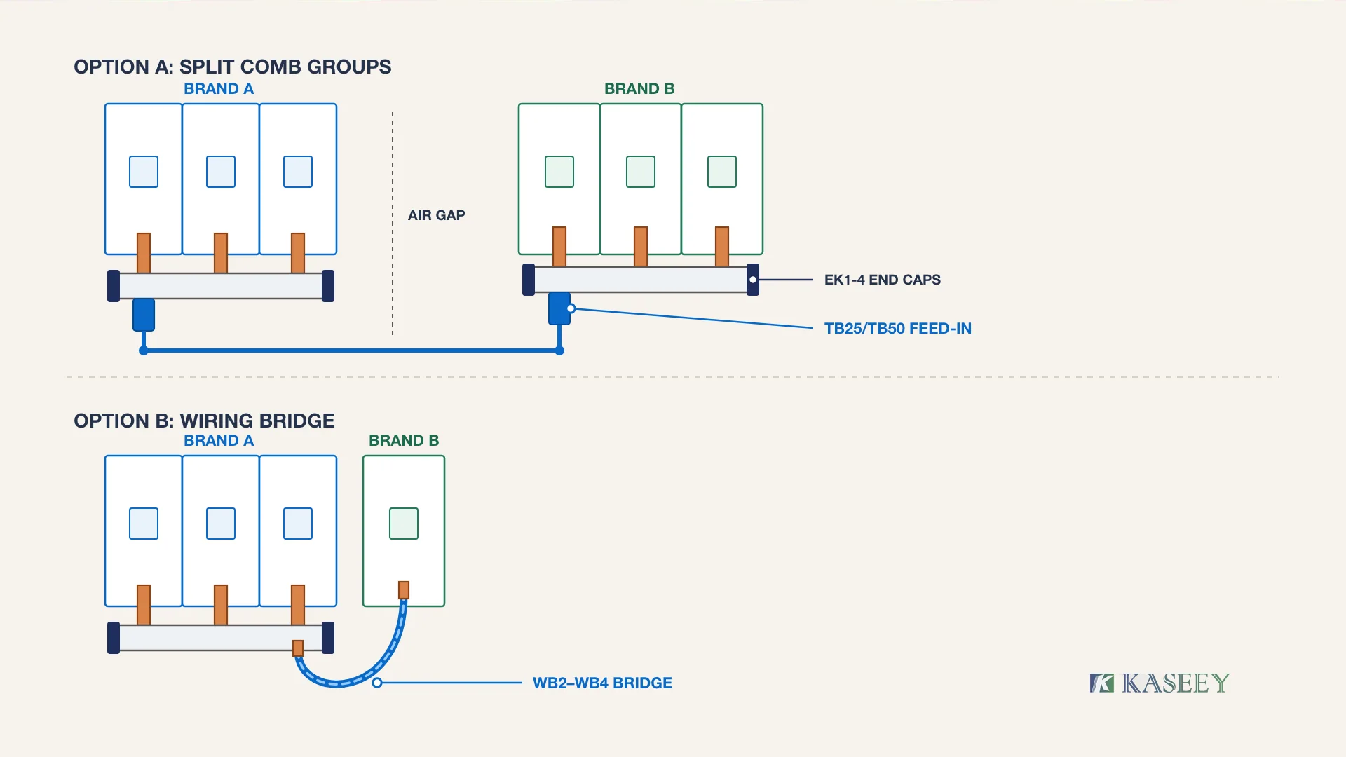
| Two multi-pole groups (3+ MCBs per brand on the same DIN rail) | Split into two brand-isolated comb busbar sections with independent parallel feeders | Brand-matched pin-type P-1L или fork-type M6 comb busbars + EK1-4 end caps + TB25/TB50 feed-in connectors | Maintain full creepage setback on cut ends and verify incoming feeder rating across both groups |
| Single replacement MCB (1–2 poles) added beside an existing row | Terminate existing comb busbar cleanly before the new breaker; jumper across the brand boundary | EK1-4 end caps + WB2/WB3/WB4 wiring bridges or ferruled flexible cable | Never clamp a solid copper comb tooth and an unferruled stranded jumper in a single-chamber cage not rated for dual conductors |
| Mixed MCB + RCBO/RCCB row within the same device family | Match phase/neutral tooth sequence (3L+3N vs 4P) or use a dedicated neutral bridge | Application-matched multi-phase comb busbar + unused-tooth protective cover (COV-1-2) | Follow neutral pole offset rules in our MCB busbar and RCBO compatibility guide |
| Repeatable OEM machinery panel combining two fixed device families | Drawing-controlled custom busbar with stepped pitch, cutout skip-teeth, or split feeder layout | KASEEY customized OEM comb busbars built to verified device CAD drawings | Requires physical sample dry-fit on both mating breaker housings and assembly-level thermal verification |
Choose brand-isolated split comb groups whenever three or more breakers of each brand share a row; switch to insulated wiring bridges or ferruled flexible links for single-device retrofits, and escalate to a drawing-controlled custom OEM busbar only for repeatable factory-verified production builds.
Split Comb Busbar Groups with End Caps and Dedicated Feed-In Connectors
Splitting a mixed-brand DIN rail into two physically separate comb busbar groups ensures that each copper comb engages only breakers sharing identical X, Y, and Z terminal coordinates. Power is distributed from the main incomer or distribution block to each comb group through dedicated TB25 or TB50 busbar feed-in connectors sized for the group’s load current.
Whenever a standard cuttable 1-meter comb busbar is trimmed to isolate Brand A from Brand B, deburr the copper cut cleanly, preserve the insulating overhang setback, and snap matching EK1-4 insulating end caps onto every exposed cut end before energizing. For exact cutting and creepage setback steps, refer to our comb busbar cutting guide.
Insulated Wiring Bridges and Ferruled Jumper Links Across Brand Boundaries
Bridging a single replacement MCB across a brand boundary with an insulated flexible link or modular WB2, WB3, or WB4 wiring bridge absorbs 2 to 6 mm of Y-axis and Z-axis terminal offset without imposing cantilever bending stress on adjacent breaker cages. Each conductor end must match the receiving terminal’s rated cross-section and torque specification.
Never force a rigid comb tooth and a loose jumper cable into the same single-chamber breaker terminal unless the breaker datasheet explicitly approves combined busbar-plus-conductor clamping. Instead, land the outgoing jumper on a dedicated feed-in terminal block or fork-type dual-chamber terminal where the busbar and outgoing wire occupy separate clamping zones.
Drawing-Controlled Custom OEM Busbars for Repeatable Multi-Device Assemblies
Panel builders and switchgear OEMs producing repeat control cabinets that intentionally combine two different modular device platforms (such as a motor-protection device beside standard branch MCBs) should never field-bend standard comb busbars. Instead, specify a drawing-controlled custom OEM comb busbar engineered with exact skip-tooth spacing, stepped pin offsets, or custom fork widths verified against both mating terminal drawings.
De-Energized Pre-Torque Inspection Before Closing Any Retrofit Busbar Row
Before torquing any comb busbar in a newly built or retrofitted distribution board, isolate and lock out the upstream supply, prove zero voltage on every phase and neutral conductor, and dry-fit the row by hand. Mechanical resistance during insertion is an immediate stop signal—never use terminal screw torque to force a misaligned comb busbar into place.
- Verify DIN-rail seating: Confirm every MCB rear latch sits flush against the 35 mm DIN rail with zero front-to-back rocking before introducing the busbar.
- Dry-fit with screws fully backed out: Slide the comb busbar into all open terminal cages by hand. Every tooth must drop freely to full insertion depth without twisting the insulating housing or lifting any breaker off the rail.
- Inspect front-to-back and vertical alignment: Sight along the busbar insulator spine from both ends of the row. Any visible step, gap between the tooth shoulder and cage entry, or pinched PVC skirt indicates an unacceptable Y-axis or Z-axis offset.
- Verify torque and pull-test: Tighten each terminal to the breaker manufacturer’s specified N·m value using a calibrated torque screwdriver, then inspect visually that every copper tooth sits squarely behind the moving clamp plate—never trapped behind the clamp jaw.
- Restore IP2X touch protection: Confirm EK1-4 end caps seal every cut end and snap protective covers (COV-1-2) over any spare unused teeth before re-energizing.
If your team is planning a multi-brand panel retrofit or specifying custom-pitch OEM comb busbars, share your target breaker terminal drawings, pole sequence, pitch, cross-section (mm²), module count, destination market, and estimated volume with our engineering team via KASEEY Contact, OEM/ODM, or [email protected] for a dimensional fit review.
Часто задаваемые вопросы
Can a fork-type comb busbar tolerate mixed MCB brands better than a pin-type busbar?
A fork-type comb busbar offers slightly more lateral tolerance around the terminal screw shank than a rigid rectangular pin, but it still cannot absorb Y-axis throat depth steps or Z-axis height offsets between different MCB brands. If the terminal screw shank diameter (M5 vs M6) or collar height differs, a fork tooth will bottom out early and create a loose, overheating joint.
What happens if a comb busbar tooth is only clamped halfway inside an MCB terminal?
A half-seated comb busbar tooth reduces the effective copper contact area and concentrates load current through a narrow edge or corner. This elevates local contact resistance, accelerates copper oxidation, softens surrounding PVC or PA66 insulation, and causes progressive screw loosening under thermal cycling—eventually triggering nuisance thermal tripping or terminal arcing.
Can you cut one comb busbar into two separate sections for two different MCB brands?
Yes, provided the comb busbar model is rated as field-cuttable and each cut section matches the exact terminal geometry (pin/fork style, pitch, and seating depth) of its own MCB brand group. After cutting, deburr the copper cleanly, verify insulating setback, install matching insulating end caps on every exposed cut end, and feed each separated group via properly rated feed-in connectors or distribution terminals.
Источники
- IEC Webstore — IEC 61439-1:2020 and IEC 61439-3:2024 — International Electrotechnical Commission (IEC); official standards catalogue defining general rules for low-voltage switchgear assemblies (IEC 61439-1:2020) and distribution boards intended to be operated by ordinary persons (IEC 61439-3:2024: outgoing circuits ≤ 125 A, assembly ≤ 250 A, original manufacturer design verification).
- IEC Webstore — IEC 60898-1:2015+AMD1:2019 and IEC 60715:2017 — International Electrotechnical Commission (IEC); official standards catalogue covering AC circuit-breakers for household and similar installations (IEC 60898-1) and standardized 35 mm mounting rail dimensions (IEC 60715:2017).
- NFPA 70: National Electrical Code (NEC) — Section 110.3(B) — National Fire Protection Association (NFPA); governing North American installation requirement for listed and labeled electrical equipment.
- UL Standards & Engagement — UL 489, UL 67, and UL 508A — UL Standards & Engagement; official standards discovery portal covering molded-case circuit breakers (UL 489), panelboards (UL 67), and industrial control panels (UL 508A).
- Штыревые 1-фазные шины P-1L | KASEEY — KASEEY; first-party specification documenting standard 17.8 mm pitch, 8–16 mm² cross-sections, and 50–80 A ratings.
- Вилочные 3-фазные соединительные шины M6 | KASEEY — KASEEY; first-party specification documenting M6 fork-type comb busbar ratings up to 25 mm² and 100 A.
- Busbar End Caps EK1-4 | KASEEY — KASEEY; first-party product page for insulating end caps used on cuttable comb busbar sections.
- Busbar Connector TB25 / TB50 | KASEEY — KASEEY; first-party product page for comb busbar feed-in connectors.
- Wiring Bridge WB2 / WB3 / WB4 | KASEEY — KASEEY; first-party product page for insulated modular DIN-rail wiring bridges.
- Customized Busbars | KASEEY — KASEEY; first-party OEM/ODM product page for drawing-controlled custom comb busbar manufacturing.