Short Answer: A comb busbar for EV charger distribution must be selected for simultaneous charging demand, rather than an assumed diversity discount. IEC 60364-7-722, clause 722.311, starts from each connection point’s maximum charging current and allows all points to operate together; reduced distribution demand needs load control. For the panel builder, the change is from diversified demand to sustained simultaneous demand, or a documented, enforced limit. Match that demand to the exact busbar reference current and feeding arrangement, then verify the complete assembly for the specified loading.
A charging board can resemble an ordinary distribution board while having a different loading assumption. Spare ways and a familiar comb do not establish capacity for charging sessions that continue for hours. The issue is the demand the assembly must support when customers actually plug in together.
This guide is for panel builders, OEM teams and distributors preparing specifications. It addresses the busbar side of that decision, without turning the product’s catalogue current into an EV approval or a complete-board verification claim.
The load that does not diversify
The EV-specific rule is in clause 722.311 of IEC 60364-7-722:2018. Its two relevant starting points are:
- Each connection point is considered to operate at its rated current or its permitted configured maximum charging current; the final-circuit demand factor is 1.
- All connection points can operate simultaneously, so the supplying distribution circuit uses diversity factor 1 unless load control is provided.
The configured maximum is not an informal expectation about vehicle use. The cited edition restricts access to that configuration. Record the supported maximum for the project; do not substitute the driver’s usual charging pattern.
Ordinary-board experience may suggest that every outgoing circuit will not draw its maximum together. That expectation is precisely what an uncontrolled charging row cannot borrow. Several vehicles can remain connected and demanding current through the same operating period.
This is a design assumption, not a claim that every vehicle always draws full current. A lighter session today does not establish the maximum demand the board must accommodate tomorrow. Prepare the load schedule by phase and by the common conductor that carries the connected charging demand.
What the assembly defaults assumed instead
A lower assumed loading may already be embedded in an ordinary assembly specification. IEC 61439-2:2011, clause 5.4 and Table 101, gives the following assumed outgoing-circuit loading where the assembly manufacturer and user have not agreed actual load currents:
| Distribution circuits | Assumed loading factor in the cited 2011 table |
|---|---|
| 2-3 | 0.9 |
| 4-5 | 0.8 |
| 6-9 | 0.7 |
| 10 or more | 0.6 |
These are edition-specific assembly assumptions. They are not comb busbar derating coefficients, and this historical table does not replace choosing the applicable assembly part and edition for the project.
AccuPanels’ EV charging hub electrical-readiness discussion makes the consequence concrete: a 12-way charging board verified using that default represents about 60% of the simultaneous load the chargers could demand. This is that source’s illustration of the verification assumption, not a Kaseey test result or a statement that every charging board has that limitation.
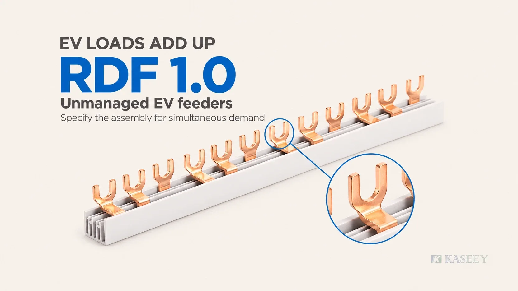
Specify rated diversity factor, or RDF, of 1.0 for the uncontrolled charging-feeder group and obtain assembly evidence matching the agreed currents. In the IEC 61439 framework, RDF describes an assembly’s simultaneous-loading capability; it is not a rating conferred on a loose busbar. Resolve the loading assumption before comparing component prices.
The procurement question is therefore specific: does the offered board’s verification cover the declared charging-feeder loading? A list of individual breaker ratings and a busbar reference current does not answer that question by itself.
Sizing a comb busbar for EV charger distribution at RDF 1
Start with the declared maximum current of every charging point. Allocate the loads to their actual phases, identify the demand carried by each shared conductor, and apply no uncontrolled-charging diversity discount. Then compare that schedule with the proposed busbar article and the complete assembly’s verified capability.
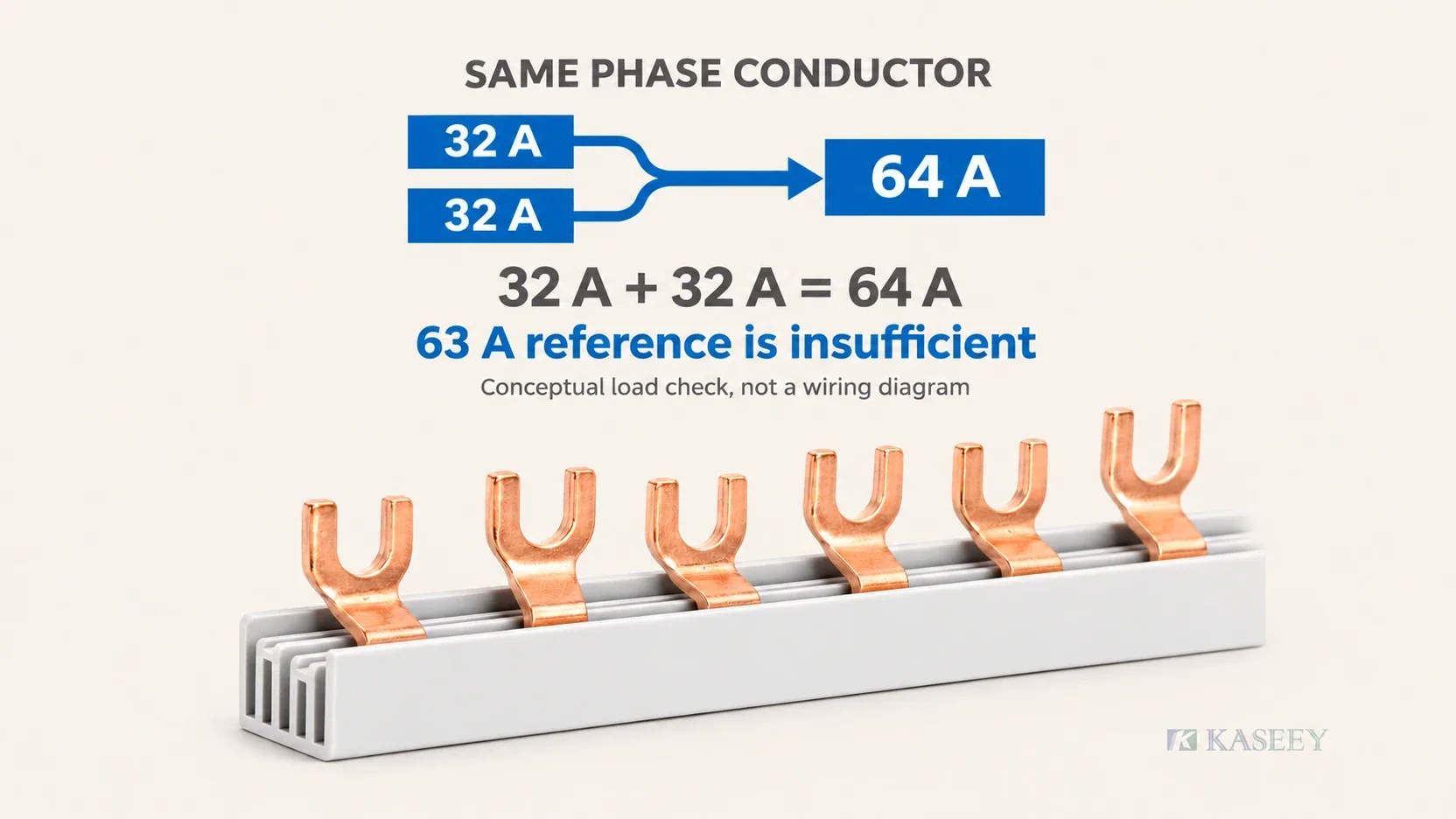
Consider two single-phase 32 A charging points supplied on the same phase conductor:
32 A + 32 A = 64 A.
That simultaneous demand exceeds a 63 A reference current. The fact that both chargers might not draw their maximum during a short observation does not close the gap. If the chargers are assigned to different phases, assess each phase separately; adding unrelated phase currents into one conductor calculation would also be wrong.
Kaseey’s 3-phase M6 fork-type busbar publishes the following cross-section and reference-current options:
| Sección transversal del conductor | Published reference current |
|---|---|
| 8 mm² | 50 A |
| 10 mm² | 63 A |
| 13 mm² | 70 A |
| 16 mm² | 80 A |
| 25 mm² | 100 A |
For this 3P product, the published fork width and length are both 12 mm, with 17.8 mm device distance. These dimensions still need to match the selected device interface. The 25 mm² / 100 A entry is a catalogue option to investigate when the design reaches that current class; it does not establish an approved continuous-duty charging assembly.
A three-phase board requiring neutral connections may instead involve Kaseey’s separate 3L+3N M6 configuration. Its current public page lists reference-current options only up to 80 A. Do not transfer the 3P product’s 100 A entry or fork geometry to that configuration merely because both pages say M6.
When the selected row cannot support the calculated demand, there are three valid design routes:
- Move to a suitable higher-capacity selection: confirm its documented interface, feeding conditions and assembly verification.
- Split the distribution: provide separately designed rows or sections and check the shared upstream path as well.
- Enforce a load limit: use a documented control ceiling that keeps the relevant currents within the selected design’s capability.
A larger catalogue entry is only the start of a revised selection. Review the connected devices, feed connection and common supply path as a system; improving one component does not resolve a restriction elsewhere in the board.
Feed position matters more, for longer
The load schedule must be considered alongside the selected feed arrangement. Where current enters changes which portions of the busbar carry the combined outgoing demand. Under sustained charging, the heavily loaded path can remain loaded throughout the session.
That makes an undocumented feed substitution a poor way to resolve a failed selection. A photograph of a centre-fed row is not evidence of the current permitted for another article or terminal arrangement. Conversely, a manufacturer-documented feeding condition should be assessed on its own stated terms.
Keep the article number, intended feed point and incoming connection together in the assembly specification. Any change to that arrangement needs review against the documented product and board design. The separate explanation of current paths and feed-specific ratings is in Comb Busbar Current Ratings: End Feed vs Centre Feed.
Hours at temperature
Sustained charging removes the assumption of long unloaded pauses. The concern is not only the conductor section: the fork-to-terminal contacts and the other common connections must remain suitable while the demand persists.
Home Electrical Supply Limits for EVs and Heat Pumps explains why an empty consumer-unit way is not proof of capacity. The main switch, busbar assembly, protective devices, neutral connections and terminals all need assessment; loose, damaged or incorrectly terminated connections can overheat, and charging can continue for several hours.
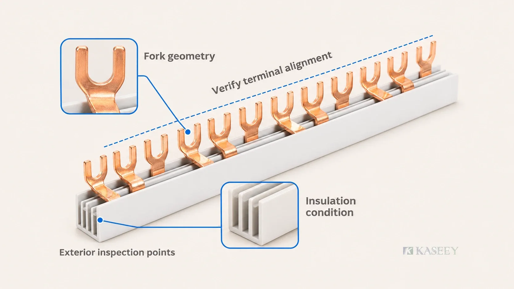
For a panel builder, this turns marginal contact into an acceptance issue. A fork outside its intended clamping position, an incompatible terminal depth in a mixed row, or a connection found loose after thermal cycling warrants correction and review. Do not accept apparent alignment from the front as proof that every contact is properly engaged.
Have qualified personnel check the actual device combination against its assembly instructions, with equipment safely isolated for physical inspection. Record fork condition, insulation condition, intended contact position and any inconsistent terminal alignment. These are checks on the proposed assembly, not a new installation procedure or a universal tightening instruction.
Uso How to Install a Comb Busbar for the separate seating and assembly task, and the Comb Busbar Incoming Inspection Checklist for the receipt checks. Both support the specification rather than replace design verification.
Read any temperature-rise evidence against its stated reference temperature and assembly conditions. The background distinction is covered in Copper Busbar Current Capacity. Kaseey’s product pages do not publish a charging-specific continuous-load correction factor, so this guide supplies no invented temperature limit or percentage reduction.
When load management earns the diversity back
The exception in clause 722.311 is load control, not optimism. The cited IEC edition defines load control around preventing the sum of dedicated-circuit currents from exceeding a predetermined value. A control system can therefore change the design demand only when its enforced limit actually governs the circuits under consideration.
State that limit in the assembly specification and identify which charging points it covers. Check how the site power ceiling translates into currents on the actual phase arrangement. A site-wide power target alone does not demonstrate that every row and phase remains within its permitted current.
The designer also needs a documented response to lost communications, unavailable measurements or a bypassed controller. If those conditions allow the load to exceed the selected design basis, the mere presence of management software has not established a lower demand for that design.
Keep the controlled ceiling and charging configuration under the agreed change process. Adding another charging point or raising a setting can change the demand the board must support. The revised setting needs assessment before the existing selection is reused.
In procurement language, “load management included” is incomplete. Ask for the enforced ceiling, the covered circuits and the evidence supporting operation within that ceiling. Size against that design basis, not a dashboard average or a predicted charging schedule.
Boundary: what this guide does not select
RCD type, DC residual-current protection, PEN-fault measures and the charger itself belong to the exact protection and complete-installation design and are outside this busbar guide. As a historical category example, Schneider Electric’s archived Resi9 R9HPDK4431EV20 product record identifies a preassembled board with an EV-associated circuit; this is not a current-availability statement, a Kaseey compatibility claim or an endorsement.
Specification checklist
Send a load-and-product schedule that the panel manufacturer can verify. Include:
- Charging points and currents: simultaneous point count, each point’s rated or controlled configured maximum, and its phase assignment.
- Enforced control limit: whether a limit exists, its covered circuits and phases, and its documented operating constraints.
- Target loading: RDF 1.0 for the uncontrolled charging-feeder group, or the agreed controlled design basis.
- Busbar selection: exact order model and Article No., cross-section, published reference current and intended feeding arrangement.
- Interface and mapping: fork interface, device series, pole arrangement and phase/neutral sequence.
- Row dimensions: finished length and module count from the selected product row, together with quantity.
- Assembly evidence: the applicable assembly specification and verification covering the declared simultaneous or controlled demand.
Keep these fields together when requesting a quote or approving a substitute. A response that changes the conductor section, phase/neutral configuration or feed arrangement should identify the change explicitly so the board designer can reassess it.
The broader worksheet is in Cómo seleccionar una barra colectora MCB. For charging distribution, its inputs must begin with the simultaneous demand or the enforced limit; the ordinary-board diversity assumption is not a shortcut.
Preguntas frecuentes
Can a standard 63 A comb busbar feed two 32 A EV chargers?
Not when both unmanaged 32 A charging points load the same phase conductor: 32 A + 32 A = 64 A, exceeding a 63 A reference current. Re-select suitable capacity, split the distribution or enforce a documented load ceiling. For different phase assignments, assess each conductor separately and verify the complete assembly.
Is there such a thing as an EV-rated comb busbar?
An EV label is not a substitute for a defined product rating and assembly verification. Kaseey’s cited M6 pages publish reference currents and dimensions, not an EV-specific rating or certification. Select the exact bar under its documented conditions and obtain the complete board’s applicable IEC 61439 verification for the intended charging load.
Does centre feeding fix an undersized bar?
No, not as an undocumented workaround. Moving the feed changes current paths but does not prove that the selected article and assembly support the sustained demand. Confirm any manufacturer-declared feed-specific capability and the complete design; see the end-feed versus centre-feed guide.
Can I apply diversity if the chargers have load management?
Yes, where the control system enforces the limit used for the design. State that ceiling and its scope in the assembly specification, translate it into the relevant conductor currents, and document operating constraints. Installing management software does not justify sizing against an expected average demand.
What changes if the board also feeds ordinary circuits?
Assess the uncontrolled charging group at diversity 1.0 and the ordinary circuits using their agreed applicable loading assumptions. Combine the resulting demands by phase and shared conductor, then check the incoming path, busbar selection and complete assembly. Keep any enforced charging limit explicit in that calculation.
Fuentes
- IEC 60364-7-722:2018, Supplies for electric vehicles – IEC original text in a public standards preview; clauses 722.3.6 and 722.311.
- IEC 61439-2:2011, Power switchgear and controlgear assemblies – IEC original text in a public standards preview; clause 5.4 and Table 101, specifically the cited historical edition.
- EV Charging Hub Electrical Readiness: PCC to Feeder Pillar – AccuPanels; attributed secondary explanation and 12-way default-loading illustration, not Kaseey testing.
- Home Electrical Supply Limits for EVs and Heat Pumps – Energy and Electricity; qualitative sustained-demand and connection-condition discussion.
- Resi9 preassembled distribution board R9HPDK4431EV20 – Schneider Electric Denmark; archived product-category example only.
- Kaseey, Fork Type 3-Phase Busbars M6 and Fork Type 3L+3N Busbars M6 – the two official product records linked individually in the sizing section; source of all Kaseey product values and the configuration distinction in this article.