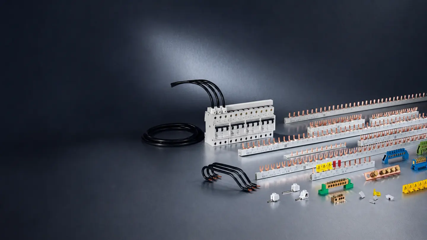
An 80 A comb busbar is no longer enough whenever the grid incoming supply rating plus solar photovoltaic (PV) and battery energy storage system (BESS) backfeed currents sum above 80 A on a shared busbar rail without upstream current-limiting protection. In a conventional single-source panel, the main incoming breaker caps busbar current. Once a solar inverter or hybrid battery system feeds power into the same rail from a second point, both sources can supply heavy downstream loads simultaneously without tripping the main breaker.
This engineering guide defines busbar summation for solar battery installations across two regulatory frameworks: European and international modular DIN-rail assemblies governed by IEC 61439-3:2024 and IEC 60364-7-712:2025, and North American panelboards governed by NFPA 70 (NEC) Section 705.12. Because KASEEY manufactures passive distribution busbars, copper bars, pan assemblies, and feed-in connectors rather than inverters or circuit breakers, the sizing thresholds below focus strictly on conductor ampacity, feed geometry, and compliant hardware upgrades.
Why Solar and Battery Backfeed Breaks Single-Source Busbar Protection
Busbar summation occurs in solar and battery distribution boards because Kirchhoff’s current law allows grid current and inverter backfeed current to converge in the same copper rail toward shared loads. Because the main grid breaker only senses utility current and the inverter breaker only senses generation current, neither device trips when their sum exceeds an 80 A comb busbar rating.
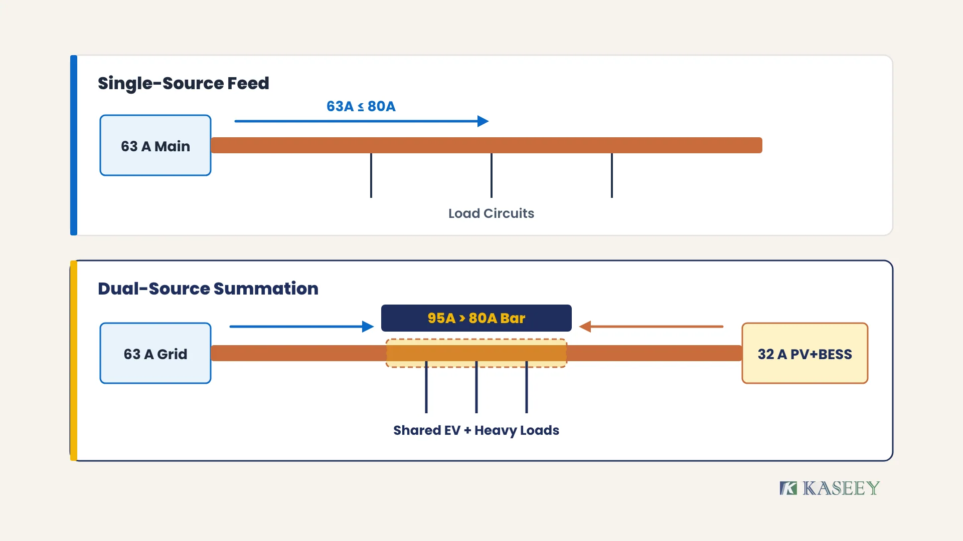
Consider a typical residential or light-commercial DIN-rail sub-board with a 63 A main incoming switch-disconnector or main breaker on the left end of a standard 16 mm2 (80 A) comb busbar. Before solar or storage is added, the 63 A main breaker guarantees that total load current on the rail cannot exceed 63 A continuously—leaving a comfortable 17 A thermal margin below 80 A.
Now add a 32 A hybrid solar-and-battery inverter connected to the same comb busbar, plus heavy outgoing loads such as an EV charger, heat pump, and kitchen circuits seated between the two sources. During peak afternoon or evening discharge, the grid can supply 60 A from the left while the battery and solar inverter simultaneously inject 30 A from the right. The busbar segment feeding those central loads carries 90 A continuously—12.5% above an 80 A comb busbar ceiling—while the 63 A main breaker sees 60 A and the 32 A inverter breaker sees 30 A. Both protective devices remain comfortably below their trip thresholds while the busbar copper and PVC insulation overheat.
Busbar Summation Rules: IEC 61439-3:2024 vs NEC 705.12
IEC distribution-board standards and North American NEC panelboard codes prevent multi-source overheating using different summation rules. Under IEC 61439-3:2024 (Annex BB and Annex CC) and IEC 60364-7-712:2025, modular DIN-rail busbars must handle the full sum of simultaneous sources unless current is limited; under NFPA 70 Section 705.12, opposite-end backfeed allows a 120% panelboard busbar allowance.
| Standard & Market Scope | Governing Provision | Core Busbar Summation Rule | Practical Effect on an 80 A / 100 A Rail |
|---|---|---|---|
| IEC / EN Modular DBOs (Europe & Global IEC) | IEC 61439-3:2024 (Annex BB Prosumer PEI, Annex CC Parallel Sources) & IEC 60364-7-712:2025 | Busbar rated current must be ≥ I_grid + I_PV/BESS (sum of simultaneous supply ratings) unless upstream overcurrent or assembly design limits total current | A 63 A grid supply + 32 A solar/battery breaker sums to 95 A, disqualifying an 80 A comb busbar |
| North America Panelboards (UL 67 / NEC) | NFPA 70 (NEC) Section 705.12 Load-Side Source Connections | Opposite-end 120% rule: I_main + 1.25 × I_inverter ≤ 1.20 × I_busbar; arbitrary breaker placement requires 100% sum rule (I_main + 1.25 × I_inverter ≤ I_busbar) | Applies to UL-listed panelboard busbars (typically 100 A–225 A); never apply NEC 120% relief to IEC DIN-rail comb busbars |
Quy tắc quyết định: Size IEC DIN-rail comb busbars to at least 100% of the sum of all simultaneous incoming and backfeed device ratings (I_busbar ≥ I_grid + I_PV + I_BESS); reserve the 120% opposite-end calculation strictly for North American NEC 705.12 panelboard installations verified by local Authority Having Jurisdiction (AHJ) rules.
IEC 61439-3:2024 (Edition 2.0, published via the IEC Webstore) specifically introduced Annex BB for prosumer electrical installations (PEIs) and Annex CC for distribution boards carrying additional parallel power sources, alongside outgoing circuit limits up to 125 A and assembly ratings up to 250 A. Meanwhile, IEC 60364-7-712:2025 expanded solar PV installation rules to cover direct battery storage circuits and island-mode operation. In North America, NFPA 70 (National Electrical Code) Section 705.12 governs load-side interconnections, breaker fastening, and permanent multiple-source plaques. Always verify local national amendments (such as VDE or BS 7671 rules) and the switchboard manufacturer’s thermal verification before finalizing assembly ratings.
Worked Examples: When an 80 A Comb Busbar Fails Solar and Battery Summation
Worked summation calculations show that even modest residential solar-plus-storage systems rapidly cross the 80 A ceiling of standard 16 mm2 comb busbars once grid, PV, and battery ratings are added. Any combination where the main supply protection plus AC-coupled PV and battery breaker ratings exceeds 80 A requires either current-limiting architecture or a higher-rated busbar tier.
| Installation Scenario | Main Grid Rating (I_grid) | Solar PV Breaker (I_PV) | Battery / Hybrid Breaker (I_BESS) | Worst-Case Summed Current | 80 A Standard Comb Busbar (16 mm2) | Required Action |
|---|---|---|---|---|---|---|
| Small 1-phase home PV only | 40 A | 20 A | None | 60 A | Compliant (60 A ≤ 80 A) | Standard 16 mm2 / 80 A comb busbar acceptable |
| Standard 1-phase home + hybrid inverter | 63 A | Combined hybrid | 25 A | 88 A | Overloaded (88 A > 80 A) | Upgrade to 100 A M5.5/M6 comb busbar or split rail |
| 1-phase home + separate PV + AC battery | 63 A | 20 A | 25 A | 108 A | Overloaded (108 A > 80 A) | Exceeds 100 A comb busbar; use pan assembly or solid copper |
| 3-phase commercial prosumer sub-board | 63 A / phase | 32 A / phase | 32 A / phase | 127 A / phase | Overloaded (127 A > 80 A) | Exceeds 100 A comb busbar; move to solid copper bar (KB) or pan assembly |
| Main service panel with 100 A incoming + BESS | 100 A | Combined hybrid | 40 A | 140 A | Overloaded (140 A > 80 A) | Dedicated solid copper distribution busbar required |
Quy tắc quyết định: Keep a standard 16 mm2 (80 A) comb busbar only when the arithmetic sum of grid and backfeed breaker ratings stays at or below 80 A (with continuous-duty derating applied for EV chargers or prolonged battery discharge); upgrade hardware immediately whenever summed current exceeds 80 A.
Two field conditions make busbar summation even more severe than the nameplate table suggests:
- Continuous-duty thermal stacking with EV chargers and heat pumps: Unlike brief domestic appliance peaks, a 32 A EV charger drawing power for 4 to 8 hours while a battery discharges at 25 A and the grid supplies the remainder holds the busbar at steady-state elevated temperature. Review continuous-load derating practices in KASEEY’s guide to comb busbar EV charger distribution.
- Misapplying single-source center-feed math: In a single-source row, moving the incoming cable from the end to the center splits current across two parallel copper halves, as explained in KASEEY’s end-feed vs center-feed current ratings guide. Under dual-source solar and battery backfeed, however, current enters from two separate points and can still converge across the same middle section unless the circuit layout and breaker ordering physically prevent load summation above the bar’s rating.
Hardware Upgrade Paths Beyond an 80 A Comb Busbar
When solar and battery backfeed pushes summed busbar current above 80 A, panel builders have four deterministic hardware paths: step up to a 100 A extended-rating comb busbar (M5.5 pin or M6 fork), electrically split the DIN-rail row via a dedicated incoming distribution block, transition to a factory-built pan assembly busbar, or build a solid copper busbar feeder stage.
Tier 1: Extended 25 mm2 / 100 A Comb Busbars (81 A to 100 A Summation)
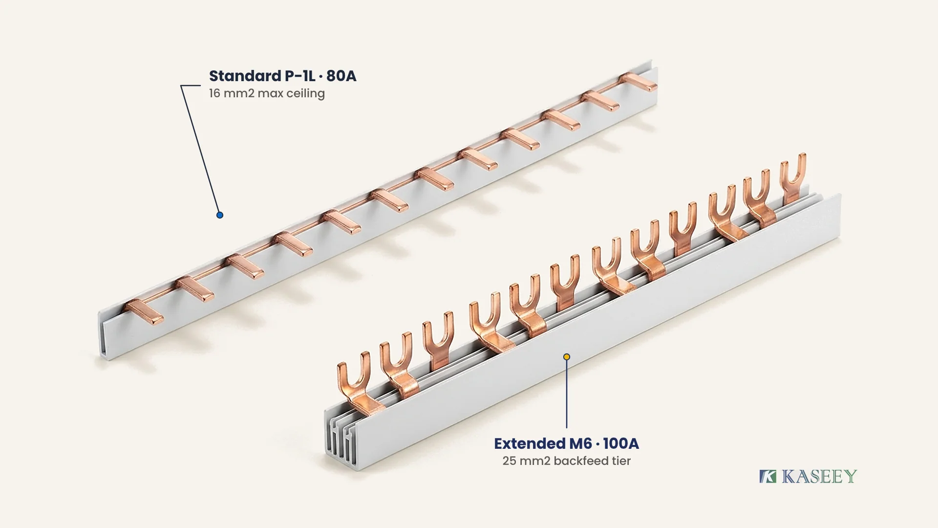
Within the dòng thanh cái lược KASEEY, standard pin-type (P, S, C45) and fork-type (G) families publish cross-section steps from 8 to 16 mm2 covering 50 to 80 A. When busbar summation sits between 81 A and 100 A—for example, a 63 A grid supply paired with a 25 A or 32 A hybrid inverter (88 A to 95 A total)—stepping up to a 25 mm2 extended comb busbar solves the rating deficit without redesigning the DIN-rail enclosure.
Crucially, the 25 mm2 / 100 A rating is not a blanket rating across all comb busbar families. In KASEEY’s published catalog, 25 mm2 / 100 A belongs specifically to the extended M5.5 pin-type and M6 fork-type product families. Before specifying an M5.5 or M6 busbar, verify that the mating breaker cage-clamp or screw-head terminals accept the heavier tooth thickness and projection, and pair incoming supply cables with rated busbar feed-in connectors (such as TB25 or TB50) rather than forcing oversized feeder wires and busbar teeth into the same breaker terminal.
Tier 2: Busbar Splitting and Dedicated Feed-In Architecture
If existing breakers cannot accept 25 mm2 comb busbar teeth, or if separate PV and battery inverters push summation close to 100 A, splitting the distribution architecture prevents backfeed current from traversing the entire load rail. By landing the grid supply, PV inverter breaker, and battery inverter breaker onto a higher-rated incoming distribution block or short primary copper rail—and feeding downstream load rows through individual overcurrent devices capped at 63 A or 80 A—each downstream comb busbar returns to a single-source protected regime. Plan feed-in placement carefully using KASEEY’s comb busbar feed-in point planning guide.
Tier 3: Pan Assembly Busbars and Solid Copper Bars (Above 100 A Summation)
Once combined grid, PV, and BESS currents exceed 100 A—common on 100 A main panels or 3-phase commercial boards with 63 A grid + 32 A PV + 32 A BESS (127 A per phase)—no standard or extended modular comb busbar is sufficient. At this threshold, panel builders transition to two higher-capacity architectures:
- Thanh cái lắp bảng: Factory-assembled multi-pole pan assembly busbar interiors use rigid, heavy-section main copper spines rated well beyond modular comb busbars while retaining structured breaker tap-offs. Compare architectural trade-offs in KASEEY’s pan assembly busbar vs comb busbar guide.
- Solid copper busbars: For custom commercial solar combiners, BESS AC-coupling cabinets, and high-current main distribution boards, solid electrolytic copper bars (KB series) allow engineers to size bar width and thickness directly to the summed ampacity and short-circuit withstand requirements of the switchgear assembly.
| Summed Busbar Current (I_grid + I_PV + I_BESS) | Recommended KASEEY Hardware Tier | Published Conductor Scope | Key Engineering Verification |
|---|---|---|---|
| ≤ 80 A | Standard Pin (P, S, C45) or Fork (G) Comb Busbar | 8 / 10 / 13 / 16 mm2 (50 / 63 / 70 / 80 A) | Confirm continuous-duty margin if EV charger is on the same rail |
| 81 A to 100 A | Extended M5.5 Pin or M6 Fork Comb Busbar | Up to 25 mm2 / 100 A (M5.5 & M6 only) | Verify breaker terminal jaw opening and use dedicated feed-in connectors (TB25/TB50) |
| > 100 A (Modular Panelboard) | Pan Assembly Busbar Interior | Multi-pole heavy-section busbar spine | Verify enclosure footprint, phase tap-off layout, and short-circuit rating |
| > 100 A (Custom / Commercial BESS) | Solid Copper Busbars (KB Series) | Engineered flat copper cross-section | Calculate temperature rise, support spacing, and bolted joint torque |
Quy tắc quyết định: Choose KASEEY M5.5 pin or M6 fork 25 mm2 (100 A) comb busbars when dual-source solar and battery summation falls between 81 A and 100 A on a DIN-rail row; switch to pan assembly busbars or KB solid copper bars whenever summed supply currents exceed 100 A.
Câu hỏi thường gặp
Can a 63 A main breaker still overload an 80 A comb busbar?
Yes. When a 63 A grid main breaker shares a comb busbar with a 25 A or 32 A solar or battery inverter breaker, simultaneous supply to downstream loads can push 88 A to 95 A through the copper rail without tripping either breaker. Always sum all simultaneous supply ratings on the rail.
Does center-feeding solve solar and battery busbar summation?
Center-feeding helps balance single-source current across two halves of a comb busbar, but it does not automatically eliminate dual-source summation. If grid power and inverter backfeed enter at different points and feed concentrated loads between them, local busbar current can still exceed 80 A unless the row is split or upgraded.
When should a panel builder switch from comb busbars to solid copper or pan assembly busbars?
Switch to pan assembly busbars or solid copper bars (KB series) whenever the summed grid, solar PV, and battery backfeed current exceeds 100 A—the upper ceiling of KASEEY’s extended 25 mm2 M5.5 pin and M6 fork comb busbars—or when commercial short-circuit withstand and enclosure thermal limits exceed modular DIN-rail hardware.
Specifying Higher-Capacity Busbars for Solar and Battery Panels
When upgrading a solar PV or battery storage distribution board beyond an 80 A comb busbar, specify the exact summed current, phase configuration (1P, 2P, 3P, 3L+3N, or 4P), terminal interface (pin, fork, or bolted copper bar), target switching device model or drawing, and destination standard (IEC 61439-3 or North American panelboard scope). Contact KASEEY’s engineering team or email [email protected] with your panel schedule and ratings to confirm M5.5/M6 extended comb busbars, KB solid copper bars, or pan assembly busbar options.
Nguồn
- IEC Webstore — IEC 61439-3:2024 and IEC 60364-7-712:2025 — International Electrotechnical Commission (IEC); official standards catalogue covering IEC 61439-3:2024 (Distribution boards operated by ordinary persons, Annex BB prosumer installations, Annex CC parallel power sources) and IEC 60364-7-712:2025 (Solar PV and battery storage electrical installations).
- NFPA 70: National Electrical Code (NEC) — Section 705.12 — National Fire Protection Association (NFPA); governing North American code for load-side interconnected power source connections and busbar ampacity limits.
- Thanh cái dạng chân cắm 1-Pha P-1L | KASEEY — KASEEY; first-party specification table documenting standard comb busbar steps from 8 to 16 mm2 (50 to 80 A).
- Thanh cái dạng chạc 3-Pha M6 | KASEEY — KASEEY; first-party specification documenting the extended M6 fork-type comb busbar family up to 25 mm2 and 100 A.
- Thanh Đồng KB Series | KASEEY — KASEEY; first-party product page for solid copper distribution busbars used above modular comb busbar ratings.
- Pan Assembly Busbar | KASEEY — KASEEY; first-party product page for factory-assembled multi-pole pan assembly busbar interiors.